133
8. The access device sends an authentication reply to the portal server. This reply carries the
EAP-Success message in the EAP-Message attribute.
9. The portal server notifies the authentication client of the authentication success.
10. The portal server sends an authentication reply acknowledgment to the access device.
The remaining steps are for extended portal authentication. For more information about the steps, see the
portal authentication process with CHAP/PAP authentication.
Portal stateful failover
Overview
The stateful failover feature supports hot backup of services on two devices. It can be configured on key
devices to avoid service interruptions caused by single point failures. When working normally, the two
devices synchronize the service information of each other. If one device fails, the other device takes over
the services.
To implement stateful failover, specify a dedicated VLAN (called the “backup VLAN”) on each device for
stateful failover packets. If both a failover link and a backup VLAN are configured, add the physical ports
at the two ends of the failover link to the backup VLAN. For more information about the stateful failover
feature, see High Availability Configuration Guide.
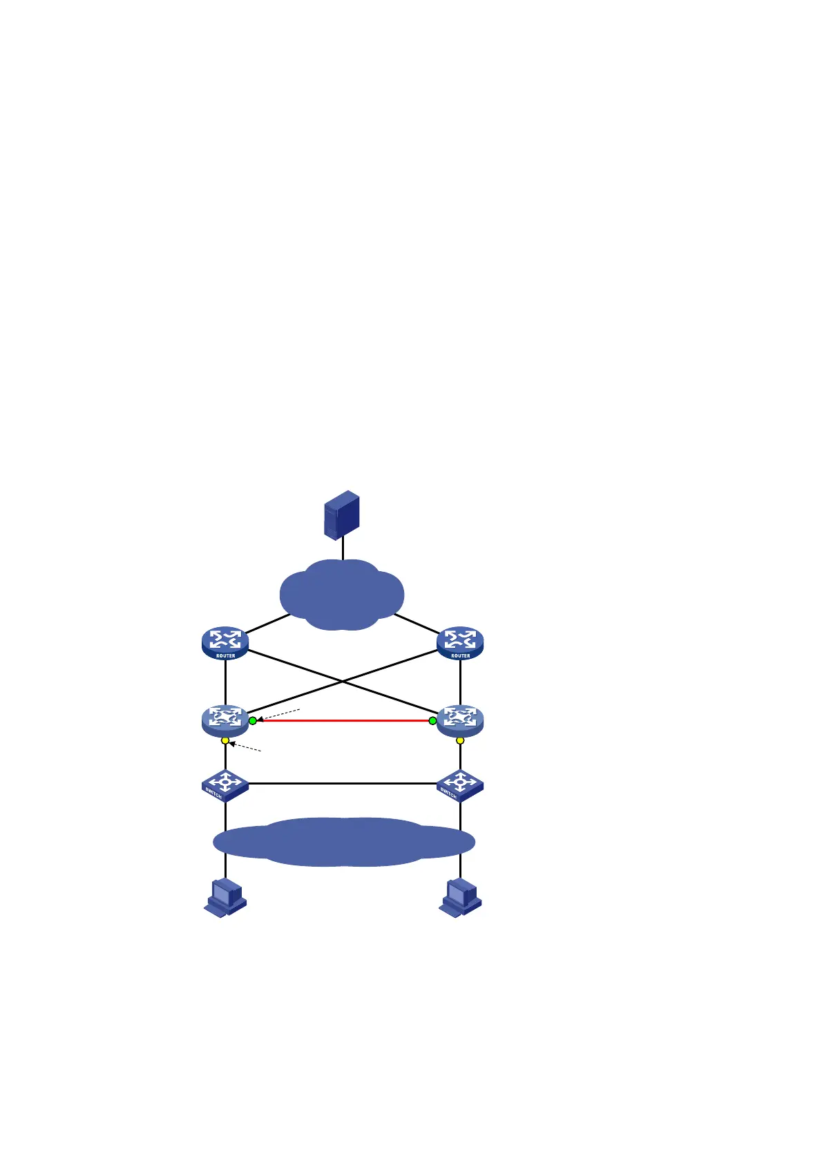
Figure 59 Network diagram for portal stateful failover configuration
Router A
Gateway A
Router B
Gateway B
Failover link
Intranet
Host A Host B
Switch A Switch B
Stateful failover
interface
Portal enabled
Internet
Server
As shown in Figure 59, users have to pass portal authentication to access the Internet. To avoid portal
service interruption caused by single point failures, you can deploy two access devices (Gateway A and
Gateway B) and configure the portal stateful failover function on them, so that they back up the portal
 Loading...