342
[SwitchB-Ethernet1/0/1] dot1x
[SwitchB-Ethernet1/0/1] quit
[SwitchB] interface ethernet 1/0/2
[SwitchB-Ethernet1/0/2] dot1x
[SwitchB-Ethernet1/0/2] quit
# Add local access user test.
[SwitchB] local-user test
[SwitchB-luser-test] service-type lan-access
[SwitchB-luser-test] password simple test
[SwitchB-luser-test] quit
# Enable ARP detection for VLAN 10.
[SwitchB] vlan 10
[SwitchB-vlan10] arp detection enable
# Configure the upstream port as a trusted port and the downstream ports as untrusted ports (a port is an
untrusted port by default).
[SwitchB-vlan10] interface ethernet 1/0/3
[SwitchB-Ethernet1/0/3] arp detection trust
[SwitchB-Ethernet1/0/3] quit
After the preceding configurations are complete, when ARP packets arrive at interfaces Ethernet 1/0/1
and Ethernet 1/0/2, they are checked against 802.1X security entries.
ARP detection configuration example II
Network requirements
Configure Switch A as a DHCP server and enable DHCP snooping on Switch B. Configure Host A as a
DHCP client. Configure Host B whose IP address is 10.1.1.6 and MAC address is 0001-0203-0607.
Enable ARP detection for VLAN 10 to allow only packets from valid clients or hosts to pass.
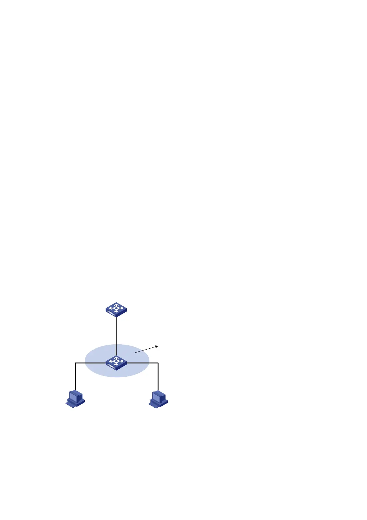
Figure 129 Network diagram
Switch A
Switch B
Host A Host B
Eth1/0/3
Vlan-int10
10.1.1.1/24
Gateway
DHCP server
Eth1/0/1
Eth1/0/3
Eth1/0/2
DHCP client
VLAN 10
DHCP snooping
10.1.1.6
0001-0203-0607
 Loading...