341
To do… Use the command…
Remarks
Display the ARP detection
statistics
display arp detection statistics [ interface
interface-type interface-number ] [ | { begin |
exclude | include } regular-expression ]
Available in any view
Clear the ARP detection
statistics
reset arp detection statistics [ interface
interface-type interface-number ]
Available in user view
ARP detection configuration example I
Network requirements
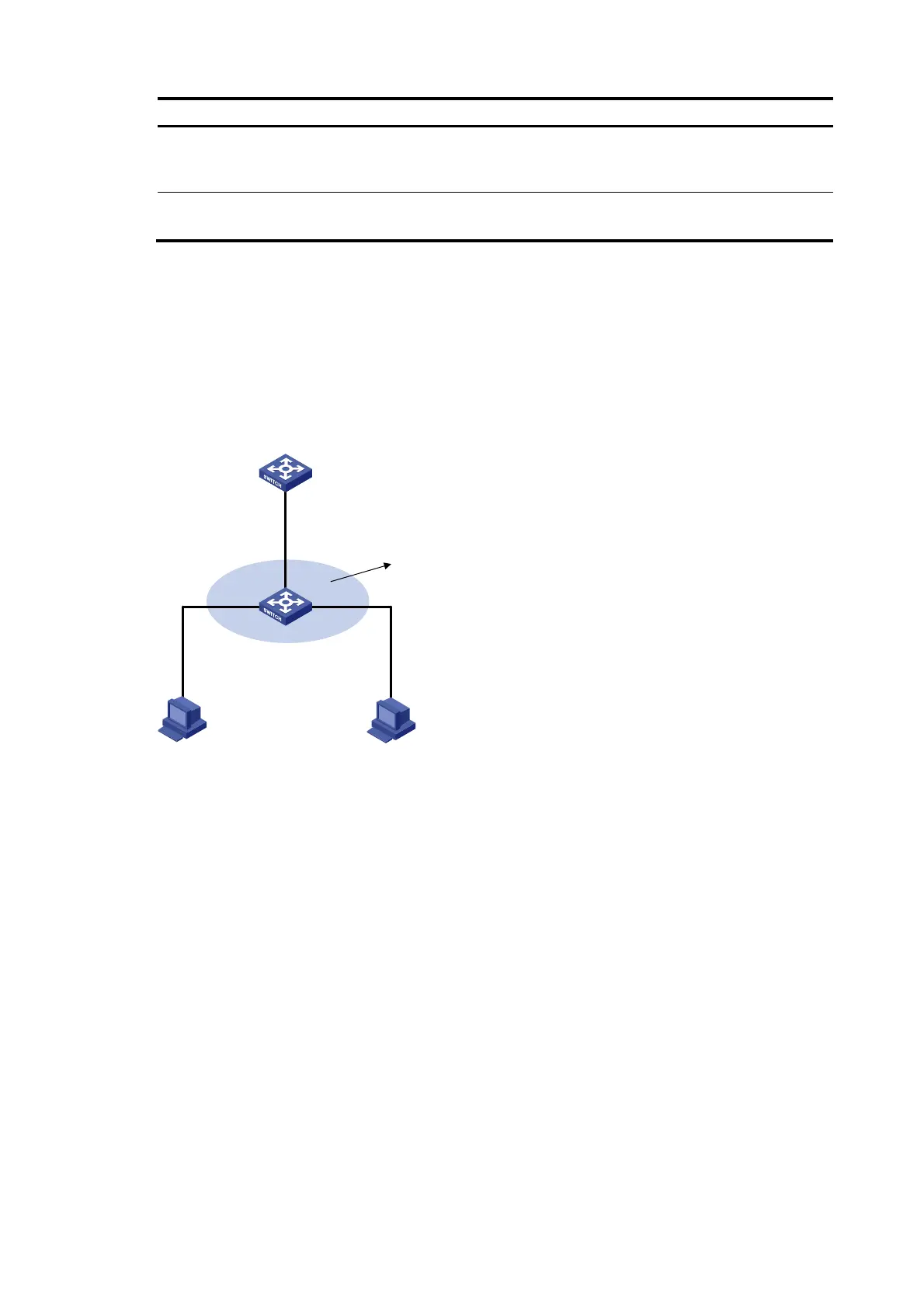
As shown in Figure 128, configure Switch A as a DHCP server and Switch B to support 802.1X. Enable
ARP detection for VLAN 10 to allow only packets from valid clients to pass. Configure Host A and Host
B as local 802.1X access users.
Figure 128 Network diagram
Switch A
Switch B
Host A Host B
Eth1/0/3
Vlan-int10
10.1.1.1/24
Gateway
DHCP server
Eth1/0/1
Eth1/0/3
Eth1/0/2
VLAN 10
Configuration procedure
1. Add all the ports on Switch B into VLAN 10, and configure the IP address of VLAN-interface 10 on
Switch A. (Details not shown)
2. Configure Switch A as a DHCP server
# Configure DHCP address pool 0
<SwitchA> system-view
[SwitchA] dhcp enable
[SwitchA] dhcp server ip-pool 0
[SwitchA-dhcp-pool-0] network 10.1.1.0 mask 255.255.255.0
3. Configure Host A and Host B as 802.1X clients (the configuration procedure is not shown) and
configure them to upload IP addresses for ARP detection.
4. Configure Switch B
# Enable the 802.1X function.
<SwitchB> system-view
[SwitchB] dot1x
[SwitchB] interface ethernet 1/0/1
 Loading...