3–4 Technical Reference Guide
Installing or Replacing Parts
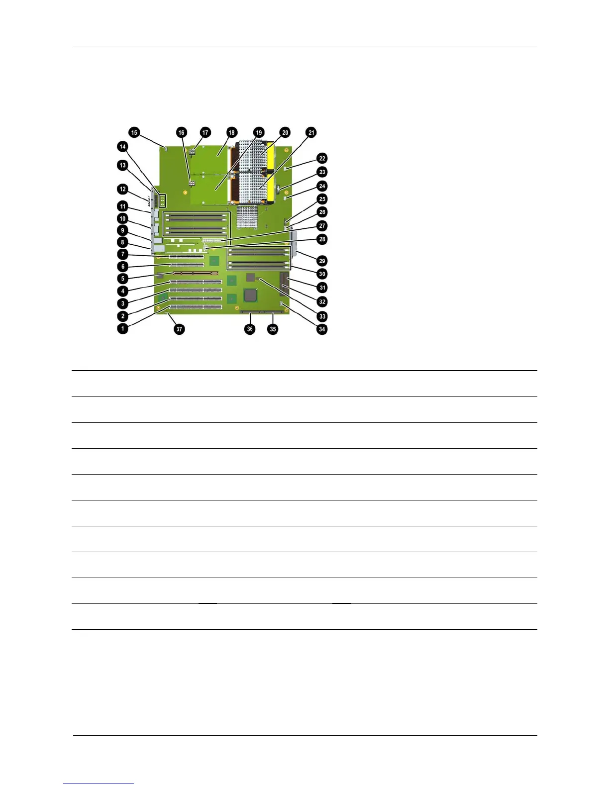
System Board Components and Connectors
This diagram identifies main system board components and connectors. For a comprehensive
system board diagram, see the label on the inside of the main access panel.
System board connectors and slots
1 Slot 7 PCI-X connector
(133 MHz 64 Bit)
11 Serial A (console)
connector
21 Processor—CPU 1 (option) 31 Primary IDE 0
connector
2 Slot 6 PCI-X connector
(66 MHz 64 Bit)
12 Diagnostic LEDs 22 Processor fan
connector—CPU 0
32 Secondary IDE 1
connector
3 Slot 5 PCI-X connector
(66 MHz 64 Bit)
13 Transfer of Control
(TOC) button
23 Battery connector 33 Front panel USB
connector
4 Slot 4 PCI connector
(33 MHz 64 Bit)
14 On-board LEDs 24 Processor fan
connector—CPU 1
34 Hard drive fan
connector
5 Slot 3 AGP Pro
8X connector
15 Chassis fan connector 25 Front control panel
connector
35 SCSI A
connector
6 Slot 2 PCI connector
(half-length 33 MHz 32 Bit)
16 Input power
connector—CPU 1 (option)
26 Memory fan
connector
36 SCSI B
connector
7 Slot 1 PCI connector
(half-length 33 MHz 32 Bit)
17 Input power
connector—CPU 0
27 Main power
connector
Hard drive activity
LED connector
8 LAN connector 18 Processor power
module—CPU 0
28 Auxiliary power
connector
9 Rear USB
connectors (3)
19 Processor power
module—CPU 1(option)
29 System board
tray release
10 Serial B connector 20 Processor—CPU 0 30 Memory module
connectors
 Loading...