Component identification and operation 14
1.
Press the Display Unit button that corresponds to the component.
o PDU—Scrolls through the PDUs in the iPDU installation
o LS—Scrolls through the iPDU load segments/Extension Bars in the iPDU installation
o Outlet—Scrolls through the Intelligent Extension Bar outlets in the iPDU installation
The current selection displays in the LED numeric display above the corresponding button.
NOTE: When a load segment has an Intelligent Extension Bar attached, the Amps numeric
LED display alternates between the load segment value and the outlet value. The Outlet
numeric LED display simultaneously alternates between the outlet number and "-" to indicate
the load segment total current.
2. Continue to press the button to scroll through the components until the display shows the desired
current selection.
The Blue UID indicator illuminates on the Extension Bar or Intelligent Extension Bar outlet to indicate
which current is displayed.
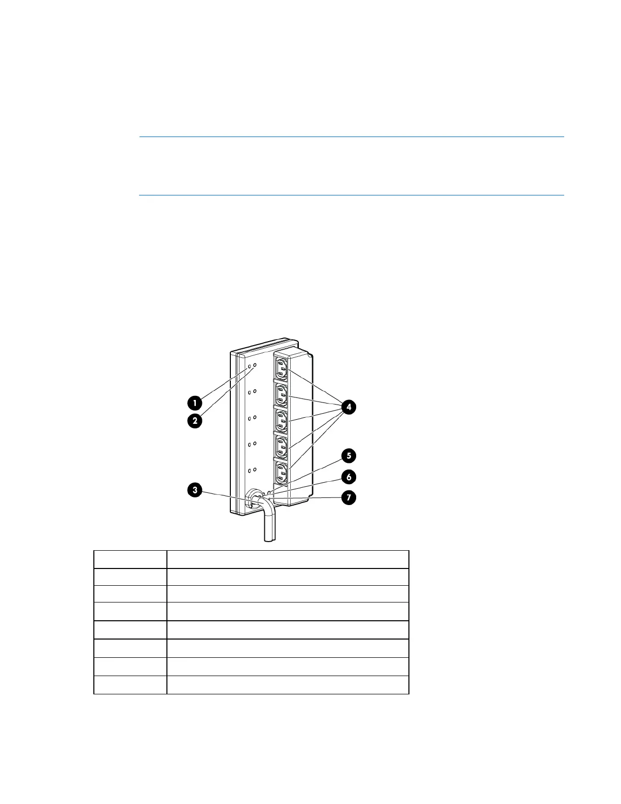
Intelligent Extension Bar components
The total rating of the Intelligent Extension Bar is 16 A.
Callout Description
1 Row of green power indicators (one for each outlet)
2 Row of blue UID indicators (one for each outlet)
3 2.4-m (8-ft) input power cord
4 Five managed 10 A, IEC-320 C13 outlets
5 Blue UID indicator for the Intelligent Extension Bar
6 Green power indicator for the Intelligent Extension Bar
7 Reset button*
*When you press the Reset button, power to the managed outlets is maintained. Management functionality is
momentarily lost while the Intelligent Extension Bar resets.

 Loading...


