Installing the HP Intelligent Power Distribution Unit 31
Extension Bar for
iPDU A
Description Extension Bar for
iPDU B
Description
A-1 Power Feed A
Load Segment 1
Outlet 1-5
B-1 Power Feed B
Load Segment 1
Outlet 1-5
A-2 Power Feed A
Load Segment 2
Outlet 1-5
B-2 Power Feed B
Load Segment 2
Outlet 1-5
A-3 Power Feed A
Load Segment 3
Outlet 1-5
B-3 Power Feed B
Load Segment 3
Outlet 1-5
A-4 Power Feed A
Load Segment 4
Outlet 1-5
B-4 Power Feed B
Load Segment 4
Outlet 1-5
A-5 Power Feed A
Load Segment 5
Outlet 1-5
B-5 Power Feed B
Load Segment 5
Outlet 1-5
A-6 Power Feed A
Load Segment 6
Outlet 1-5
B-6 Power Feed B
Load Segment 6
Outlet 1-5
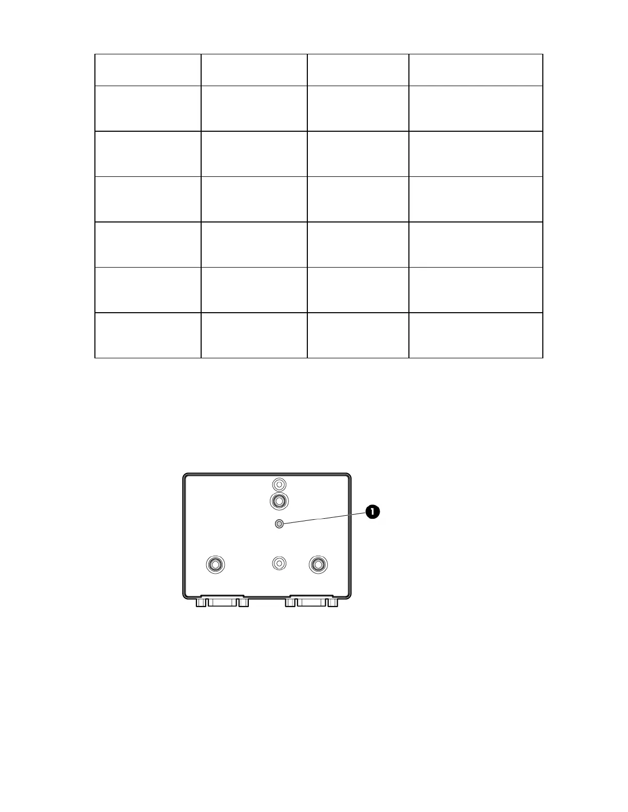
Checking the Display Unit LED indicator
If the LED indicator that is visible when the rack door is closed (1) illuminates or flashes, see the
"Troubleshooting (on page 86)" section for more information.
Connecting the network cable
Connect a standard Ethernet cable between the network connector on the Core Unit and a network jack.
This connection is used to access the iPDU through telnet or the web interface.

 Loading...


