English - 17
1. FUNCTION
The strength of the signal in the guide loop is
dependent on the length of the loop. Consequently, the
guide loop should be as short as possible, preferably
no longer than about 200 metres (700 ft). See the
picture below for examples of guide wire installation.
The longer the guide loop the lower the signal strength
and the harder it is for the Automower to follow the
guide wire. A lower signal strength means that the
mower, with a given corridor width, will be run closer to
the guide wire. Should the strength of the signal
become too low, the Automower may, for example in a
closed corner, stop following the guide wire.
To reduce the risk of the mower losing contact with the
wire in the corner, it is recommended to avoid placing
the wire at 90 degree angles. It is better to place the
wire at 2 x 135-degree angles, see the figure above.
The strength of the Guide signal also varies along the
guide wire depending on the closeness to other parts
of the guide wire and is affected by islands, heads,
passages and corners.
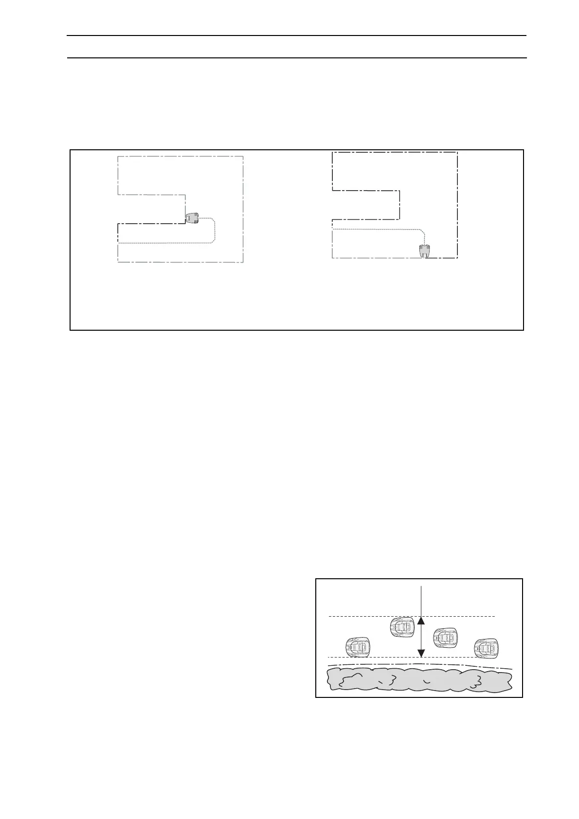
1.11 Corridor width
This section only applies to 220 AC, 230 ACX and
Solar Hybrid.
The corridor width determines the maximum distance
from the boundary wire or the guide wire that the
Automower is permitted to run when it follows the
loop or the wire on route to or from the charging
station. A low corridor width value represents a
narrow corridor while a high value represents a wide
corridor.
With a narrow corridor the Automower always runs
close to the boundary wire respective guide wire.
With a wide corridor the Automower varies how it
runs, i.e. close to and further from the boundary wire
respective guide wire. A wide corridor reduces the risk
of tracks forming.
3012-610
3012-611
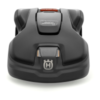
Example 2a:
Unnecessarily long guide wire
Guide loop > 300 m (1000 ft)
Example 2b:
A shorter guide wire can be
fashioned by moving the
charging station
Guide loop < 300 m (1000 ft)

 Loading...