EasyManuals Logo
Home>Hypertherm>Welding System>Powermax 125

Hypertherm Powermax 125 Service Manual

Hypertherm Powermax 125
317 pages
To Next Page IconTo Next Page
To Previous Page IconTo Previous Page
Page #123 background imageLoading...
Page #123 background image
Powermax125 Service Manual 808070 123
8 Troubleshooting and System Tests
Figure 10 Schematic for building an IGBT tester
3
4
5
6
7
8
9
11
12
13
14
15
16
2
10
17
1
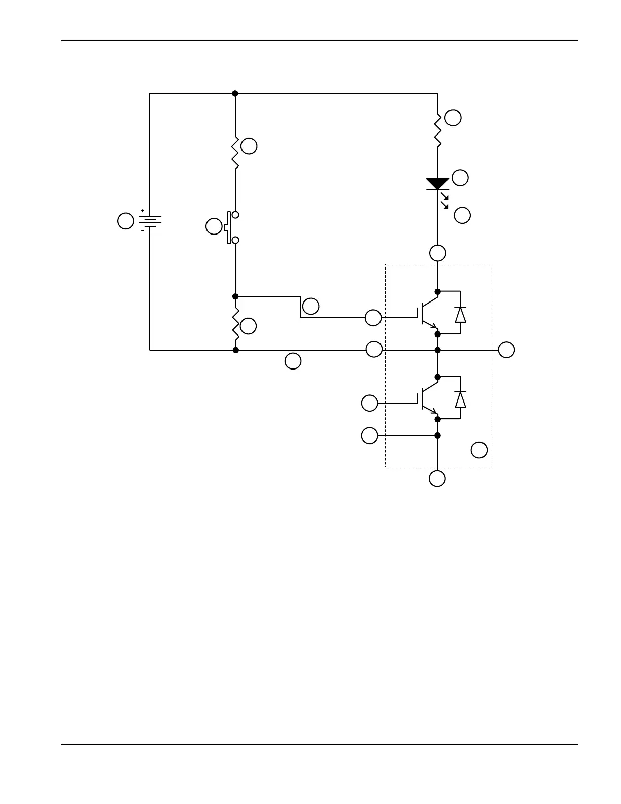
1 IGBT module to be tested (inside the dashed line)
2 Collector (“C1” or “3”)
3 Emitter (“E2” or “2”)
4 Collector, Emitter (“C2E1” or “1”)
5 Gate (“G1” or “4”)
6 Emitter (“E1” or “5”)
7 Emitter (“E2” or “2”)
8 Gate (“G2” or “6”)
9 Red minigrabber test clip
10 D1 Red LED lamp (109092)
11 R3 2.0K (009036)
12 R4 2.0K (009036)
13 9VDC battery
14 Normally open push-button switch
15 R1 3.01M (009464)
16 Black minigrabber test clip
17 Yellow minigrabber test clip

Table of Contents

Other manuals for Hypertherm Powermax 125

Questions and Answers:

Question and Answer IconNeed help?

Do you have a question about the Hypertherm Powermax 125 and is the answer not in the manual?

Hypertherm Powermax 125 Specifications

General IconGeneral
BrandHypertherm
ModelPowermax 125
CategoryWelding System
LanguageEnglish

Related product manuals