Powermax125 Service Manual 808070 205
9 – Power Supply Component Replacement
Replacing the power board
Remove the power board
Complete the instructions below while referring to the applicable figure:
Figure 74 – 480 V / 600 V CSA power board on page 207
Figure 75 – 400 V CE / 380 V CCC power board on page 208
1. Complete the following procedures:
a. See Disconnect the power and gas supply on page 166.
b. See Remove the power supply cover on page 172.
c. See Remove the component barrier on page 173.
d. See Remove the DSP board on page 203.
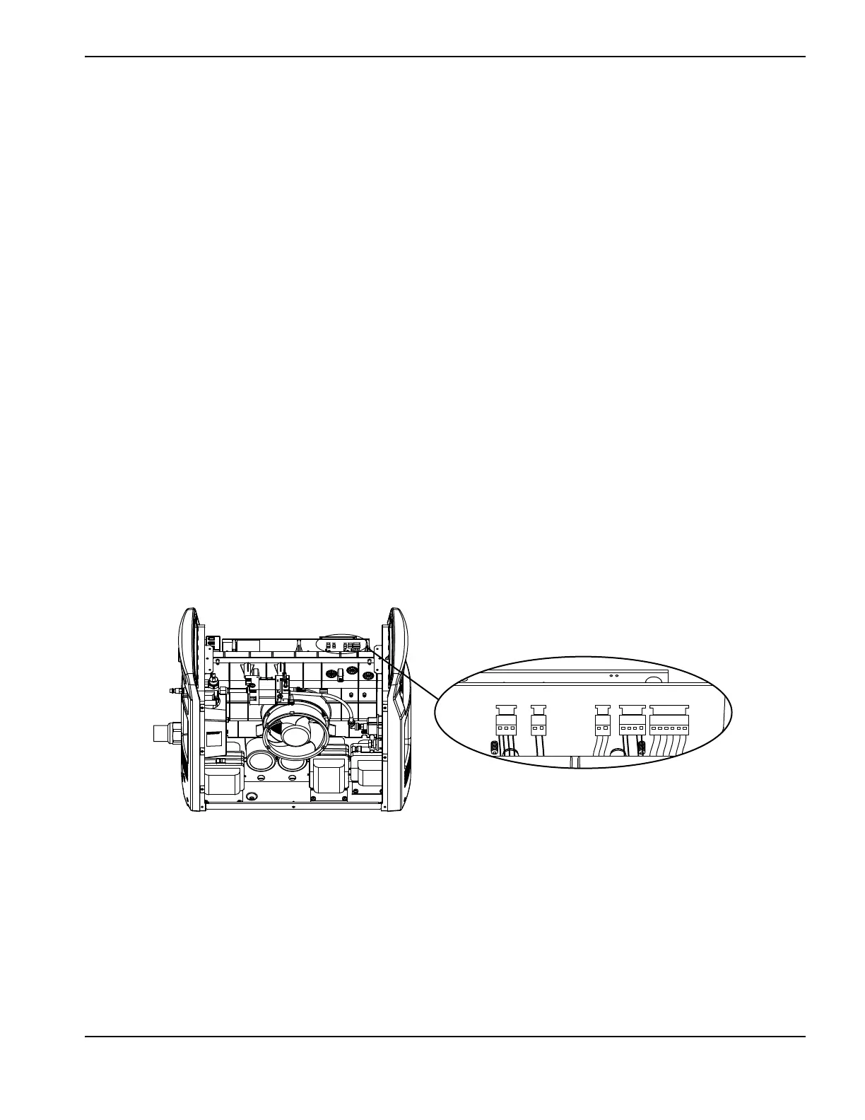
2. Unplug the 5 wire connectors located at J1, J2, J3, J5, and J6 on the component side of the power board.
Figure 73
3. Disconnect the gate drive wire connectors (J21, J22) from the power board.
4. Remove the two 4 μF capacitors from the power board.
5. Remove all the screws and bolts securing wires to the power board.
6. Remove all the remaining screws from the power board except the 7 board mounting screws and the 2 transformer
mounting screws.
Kit number Description
428123 Kit: Powermax125 power board 480 V CSA (141204)
428124 Kit: Powermax125 power board 600 V CSA (141290)
428122 Kit: Powermax125 power board 400 V CE/380 V CCC (141207)
J1 J2 J3 J5 J6
J1 J2 J3 J5 J6

 Loading...


