Powermax125 Service Manual 808070 257
9 – Power Supply Component Replacement
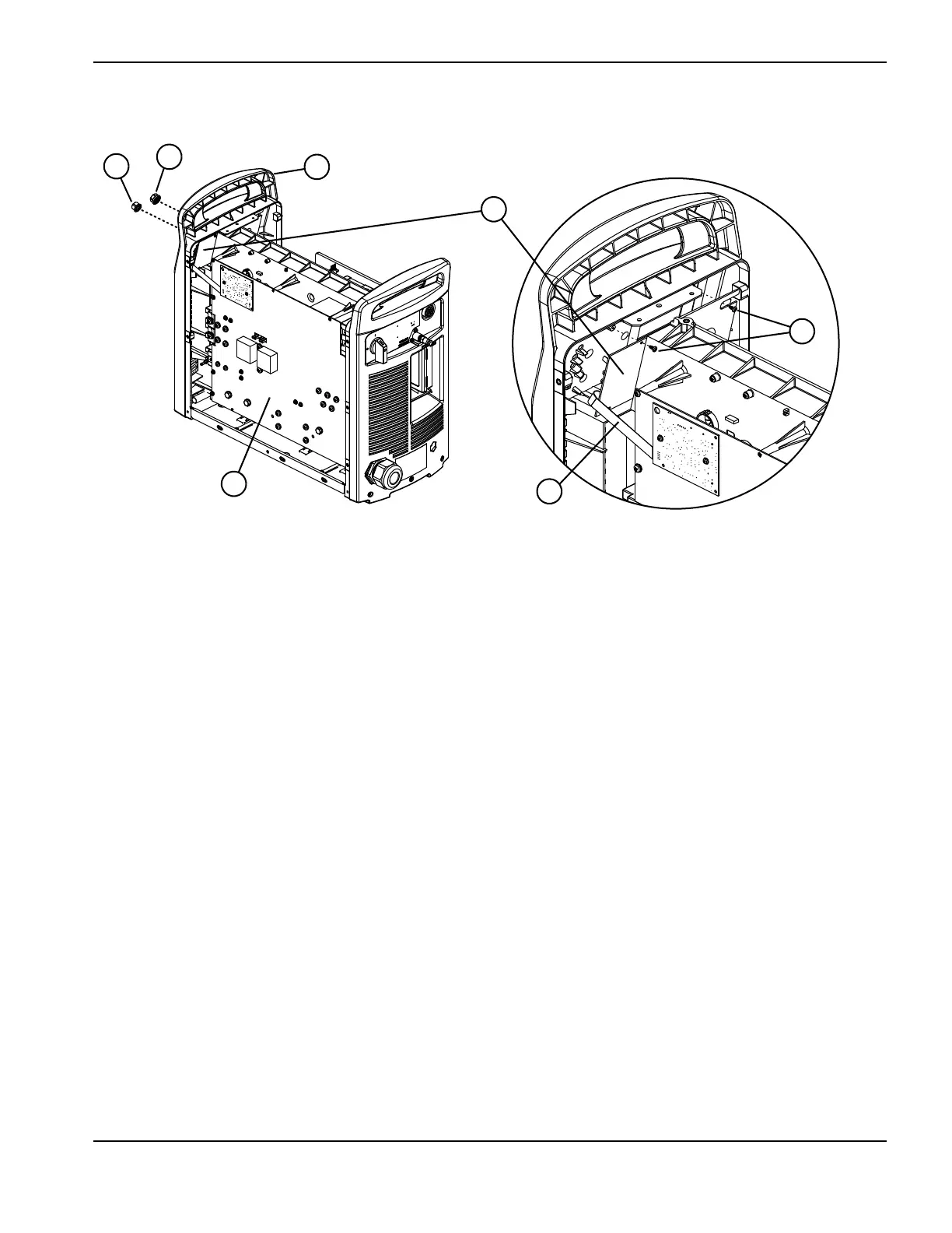
Figure 110
11. Complete the following procedures:
a. See Install the fan shroud on page 216.
b. See Install the end panel bracket on page 175.
c. See Install the component barrier on page 173.
d. See Install the power supply cover on page 172.
e. Reconnect the power and gas supply.
Replacing the rear panel
Kit number Description
428110 Kit: Powermax125 480V CSA rear panel
428112 Kit: Powermax125 600V CSA rear panel
428111 Kit: Powermax125 400V CE rear panel
428113 Kit: Powermax125 380V CCC rear panel
1 Current adjustment knob
2 Operating mode knob
3 Power board
4 Ribbon cable
5 Top mounting screws for control board
6 Control board
7 Top of front panel

 Loading...


