142 Powermax125 Service Manual 808070
8 – Troubleshooting and System Tests
Torch-related faults – continuity check
Check for continuity between the following points:
If there is no continuity between any 2 test points, replace the torch FastConnect
receptacle.
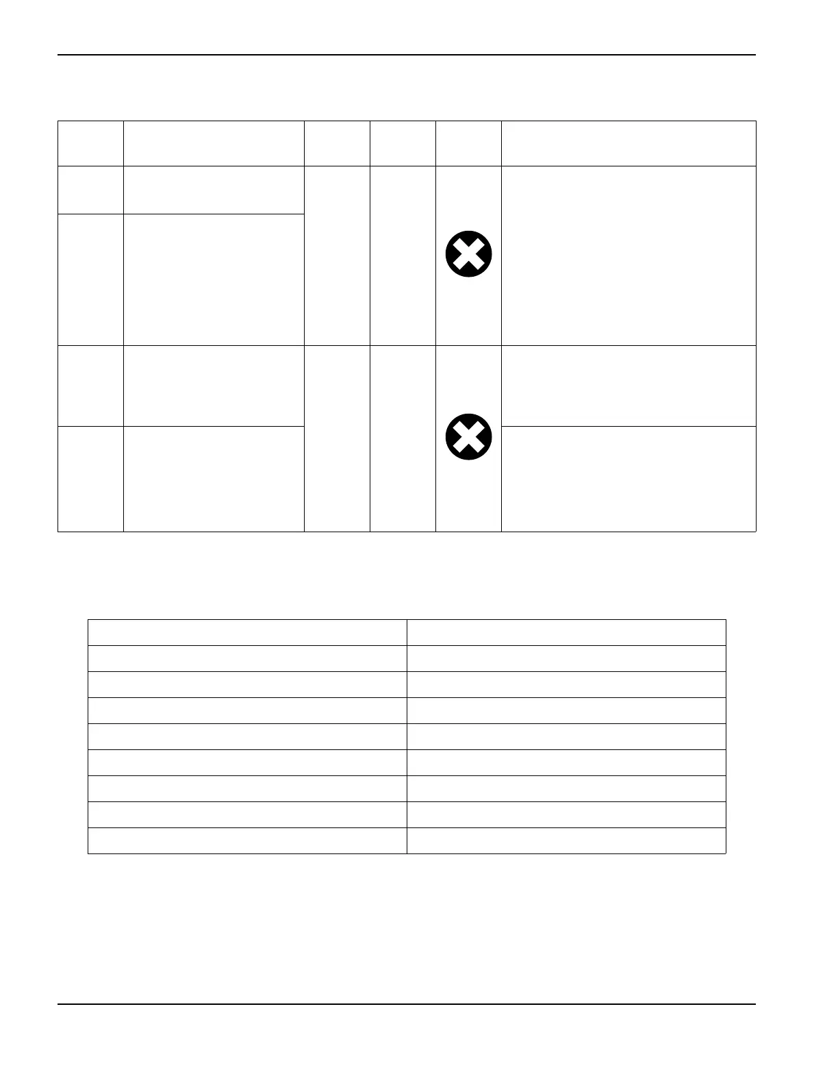
3-51-1 Inverter saturation fault (the
inverter is over current)
On On
Upper and lower inverter IGBTs are being
activated in phase rather than 180° out of
phase.
• Test the 2 inverter IGBTs in the
module.
•Perform Test 3 – Output diodes on
page 154.
• Replace the module if either is faulty.
• If necessary, replace the power board.
3-52-0 Shoot through
3-60-0 Power board
On On
The DSP does not recognize the power
board. The code is for future machines
where the current DSP board will not
work with future power boards.
3-70-0 Internal serial
communications fault
There is a fault with the communication
between the DSP and power board.
• Check the board connector.
• If necessary, replace either the DSP or
power board.
Torch FastConnect receptacle J17 on the power board
51
72
63
84
95
10 6
11 7
12 8
3-nn-n
Fault
code
Description
Power
LED
Fault
LED
Fault
icon
Solutions

 Loading...


