
Do you have a question about the Hypertherm Powermax 125 and is the answer not in the manual?
| Output Current | 30-125 A |
|---|---|
| Input Power | 15.2 kW |
| Open Circuit Voltage | 300 VDC |
| Gas Supply | Clean, dry, oil-free air or nitrogen |
| Input Power Cable Length | 10 ft (3 m) |
| Rated Output Current | 125 A |
| Gas Type | Air or nitrogen |
| Cutting Capacity | 1-1/4 inch (32 mm) |
| Pierce Capacity | 1 inch (25 mm) |
| Input Voltage | 200-600 V, 3-PH |
| Duty Cycle | 100% @ 125 A |
| Certifications | CSA |
| Maximum Clean Cut Thickness | 1-1/4 inch (32 mm) |
| Cooling Method | Fan-cooled |
| Torch Options | Hand |
User responsibilities for installing and using equipment to achieve electromagnetic compatibility.
Hypertherm's warranty for products against defects in materials and workmanship.
Overview of the Powermax125 as a portable plasma cutting system for various applications.
Technical ratings and specifications for Hypertherm power supplies.
Instructions for preparing the electrical power supply, including fuse and switch requirements.
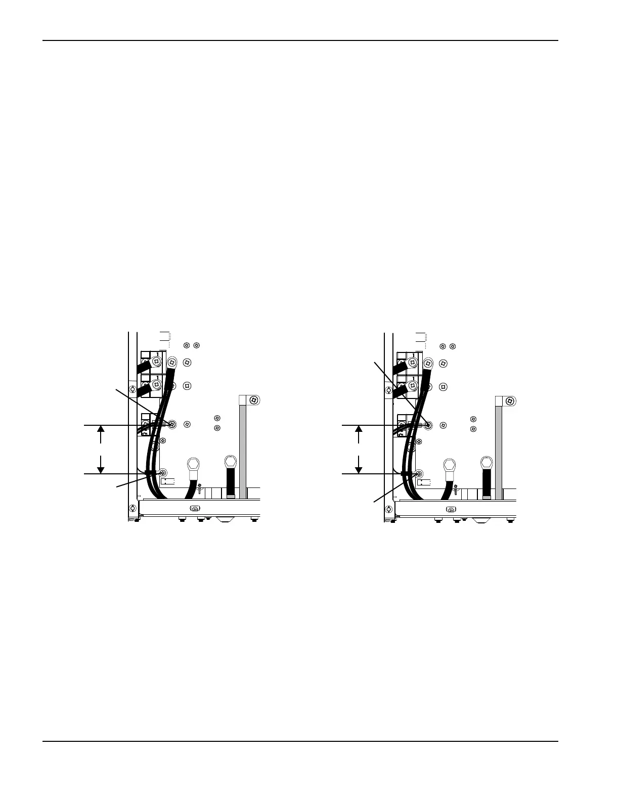
Details on connecting the Powermax125 to power, including voltage configurations and fuses.
Requirements for gas supply, including compressor or cylinder use and regulator specifications.
Procedure for connecting the gas supply hose to the power supply unit.
Tables detailing minimum inlet pressure and gas flow rates for cutting and gouging.
Detailed explanation of front panel controls like adjustment knob, selectors, and LEDs.
Understanding the information displayed on the status screen, including icons and readings.
Explanation of fault codes and icons that appear on the status screen for troubleshooting.
Step-by-step instructions for installing shield, retaining cap, nozzle, electrode, and swirl ring.
Procedure for starting a cut from the edge of a workpiece with the hand torch.
Instructions for safely piercing a workpiece with the hand torch, including angle and distance.
Step-by-step guide for performing gouging operations with the hand torch.
Troubleshooting common issues in hand cutting, such as incomplete cuts or poor quality.
Guidance on selecting consumables for different machine torch applications.
Lists of consumables for mechanized shielded, gouging, and FineCut applications.
Procedure for installing consumables into the machine torch.
Explanation of how to use cut charts for mechanized consumables and data interpretation.
Details on connecting the machine interface cable for arc transfer and plasma start signals.
Steps for setting up the torch and table, including alignment and motion system checks.
Factors affecting cut quality such as cut angle, dross, and straightness.
Procedure for starting cuts by piercing the workpiece with the machine torch.
Description of system controls and indicators, referencing Basic System Operations.
Step-by-step operational sequence from power off to power on.
Prerequisites and safety considerations for service technicians performing troubleshooting.
Overview of troubleshooting steps and references to other manual sections.
Instructions for using the Hypertherm IGBT tester to test IGBTs.
Procedures for testing IGBTs using the Hypertherm tester and troubleshooting the tester itself.
Table detailing fault categories, codes, and suggested solutions for troubleshooting.
Guide to common problems, meanings, causes, and solutions for Powermax usage.
List of system tests, their descriptions, and associated fault codes.
Procedure for checking incoming AC line voltage and output voltage of the input diode bridge.
Troubleshooting procedure for inverter temperature sensor faults (0-40-2, 0-40-3, 2-10-0, 2-10-1).
Procedure to diagnose and resolve faults related to torch stuck open or closed conditions.
Procedure to test the start signal from the torch trigger to the control board.
Procedure for testing the pressure sensor and troubleshooting readings that do not agree.
Procedure for replacing the main control board.
Instructions for removing and installing the Digital Signal Processor (DSP) board.
Procedure for removing and installing the power board.
Instructions for replacing the pilot arc IGBT module.
Procedure for replacing the inverter IGBT module.
Procedure for replacing bulk capacitors on the power board, noting polarity.
Procedure for removing and installing the transformer.
Instructions for removing and installing the PFC inductor.
Procedure for safely disconnecting power, gas, and torch before maintenance.
Lists and diagrams of replacement parts for the power supply exterior and interior.
Part numbers for consumables used in drag cutting, gouging, and FineCut applications.
Part numbers for shielded and gouging consumables for machine torches.
Detailed schematic diagram of the Powermax125 electrical system.


