152 Powermax125 Service Manual 808070
8 – Troubleshooting and System Tests
Test 2 – DC power bus
Resistance check
All resistance values must be taken with the power cord disconnected and all internal
power supply wires attached.
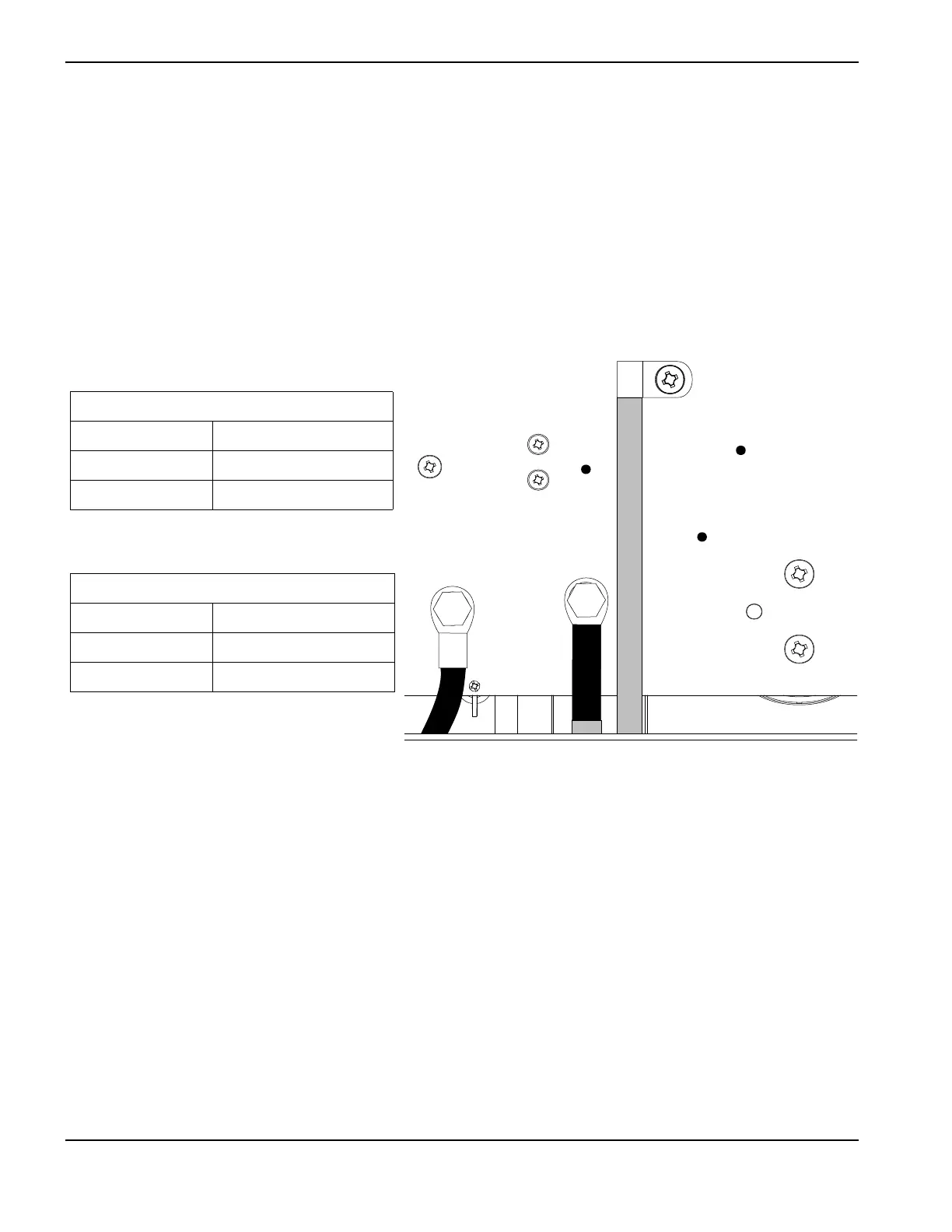
Remove the mounting screws from the bulk capacitors and pull the capacitors away from the power board.
Measure the resistances described in the following tables.
Figure 22
Replace the bulk capacitor mounting screws before you torn ON the power.
Voltage check
All voltages must be measured with the input power connected and the machine on. (See Figure 23 on page 153.)
Wear proper personal protective equipment (PPE) before testing powered equipment. All
values are ±50%. However, this range is intended only for reference. Resistance values
can vary widely depending on the type of multimeter and the polarity used to measure the
readings.
Check the inverter IGBT module voltages as described below.
The voltage measured across the bulk capacitors (half the bus voltage or the smaller
values above) should be the same before and during torch operation.
J27
WORK
LEAD
J26
+
_
TP7
TP9
TP8
W
R
B
600 V CSA
Test points Value
TP 7 and 9 25 kΩ
TP 8 and 9 25 kΩ
480 V CSA, 380 V CCC, 400 V CE
Test points Value
TP 7 and 9 18 kΩ
TP 8 and 9 18 kΩ

 Loading...


