Powermax125 Service Manual 808070 287
10 – Torch Component Replacement
Replacing the cap sensor switch
Remove the cap sensor switch
1. Complete the following procedures:
a. See Disconnect the power, gas supply, and torch on page 266.
b. See Remove the mounting sleeve on page 285.
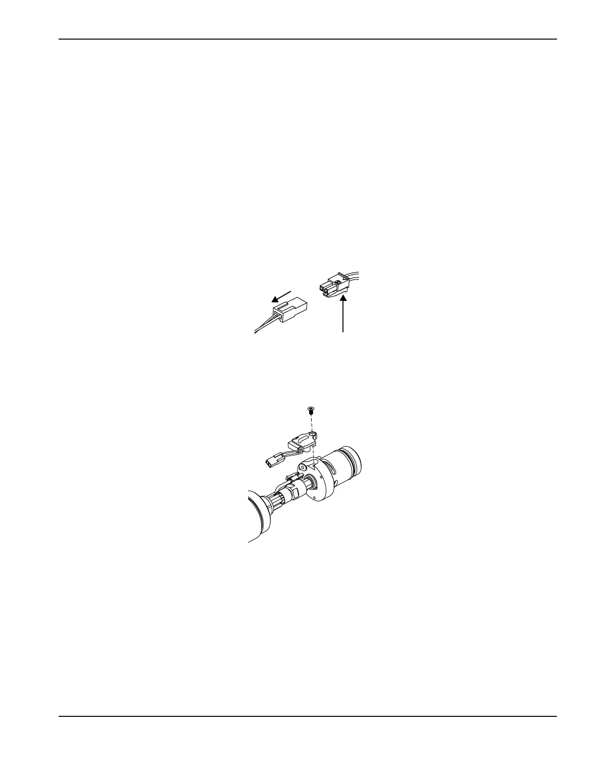
2. Disconnect the cap-sensor switch by pressing the tab on the connector and pulling the connector apart.
Figure 144
3. Remove the screw from the cap-sensor switch and remove the switch from the torch body.
Figure 145
Install the cap-sensor switch
1. Install the cap-sensor switch and screw.
2. Connect the cap-sensor switch to the torch lead.
3. Complete the following procedures:
a. See Install the mounting sleeve on page 286.
b. Reconnect the torch and gas supply, and turn ON (I) the power.
Kit Description
228720 Kit: Duramax/Hyamp/MRT 180° machine torch cap-sensor switch replacement

 Loading...


