Powermax125 Service Manual 808070 173
9 – Power Supply Component Replacement
Replacing the component barrier
Remove the component barrier
1. Complete the following procedures:
a. See Disconnect the power and gas supply on page 166.
b. See Remove the power supply cover on page 172.
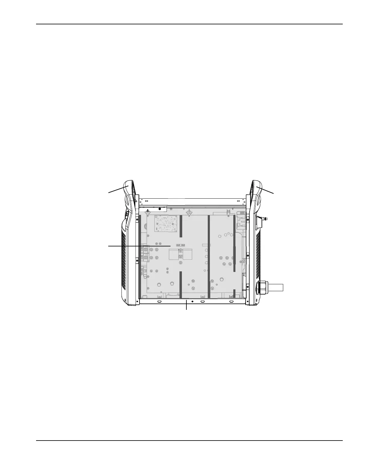
2. Remove the component barrier from the power board side of the power supply. The component barrier is flexible and
can be bent slightly for removal.
Figure 40
Install the component barrier
1. Slide the side and bottom edges of the component barrier behind the end panel edges and down to the base.
2. Bend the bottom-right of the component barrier at the perforation, and insert it between the power cord wires and
the edge of the power board.
3. Bend the top-right of the component barrier at the perforation and place over the top of the power switch.
4. Center the barrier between the front and rear panels.
5. Put the power supply cover back in place. (See Install the power supply cover on page 172.)
6. Reconnect the power and gas supply.
Kit number Description
428114 Kit: Powermax125 component barrier
Front panel
Component barrier
Rear panel
Base

 Loading...


