Powermax125 Service Manual 808070 129
8 – Troubleshooting and System Tests
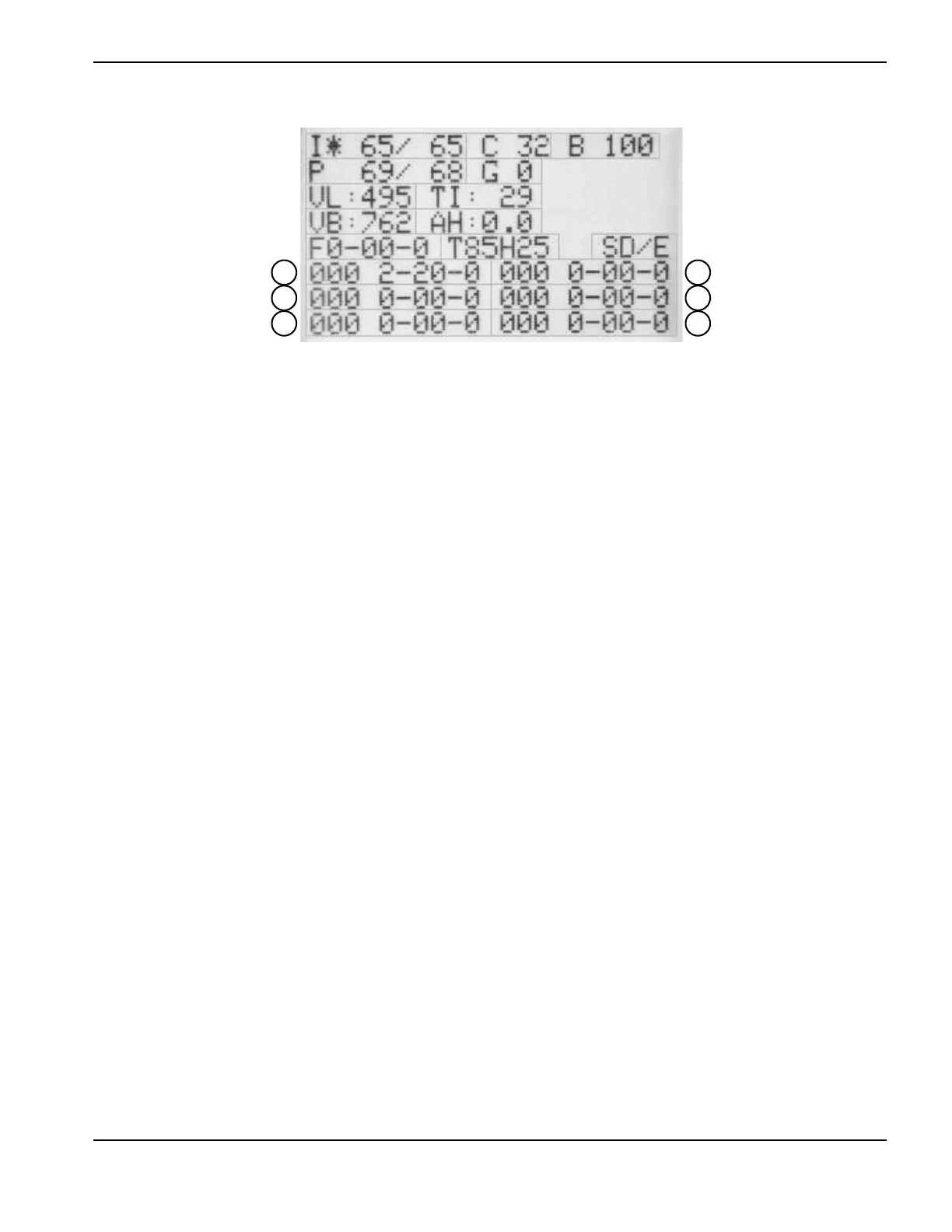
Figure 17
Fault codes beginning with zero (0-nn-n) are not recorded in the fault log.
To move the field selector (*) between fields, press the current/gas mode selector. The asterisk indicates the selected
field. You can alter the I, C, B, P, and G fields by turning the adjustment knob.
To toggle between (I) Current set/read and (P) Pressure set/read, press the automatic/manual mode selector. The LED is
illuminated when the Pressure set/read field is selected.
To exit the service screen, simultaneously press the automatic/manual and current/gas mode selectors. The operator
screen displays.
Designator Description
I Current set/read
CLCD contrast
B LCD brightness (percent)
P Pressure set/read
G Gas test enable (1)/disable (0)
VL Incoming AC line voltage
TI Inverter module temperature (°C)
VB DC bus voltage
AH Arc hours
F Live 4-digit fault code for diagnosing system errors
T Torch identifier (amperage/hand (H) or machine (M)/lead length in feet)
S Control/DSP board software versions
(callouts 1 – 6) Fault log of recent fault codes recorded by the system (0-00-0) and the
last 3 digits of the arc hour count when the fault occurred (000). Callout 1
is the most recent fault code.

 Loading...


