264 Powermax125 Service Manual 808070
9 – Power Supply Component Replacement
14. Connect the 2 wires to the pressure switch wire terminals (blue wire closest to the center panel).
15. Attach the CNC interface connector to the rear panel by tightening the 2 mounting screws to 11.5 kg-cm
(10 inch-pounds).
16. Secure the 2 ground wires to the gas filter housing by tightening the ground wire screw to 11.5 kg-cm
(10 inch-pounds).
17 . Reinstall the power cord. See Install the power cord and strain relief on page 194.
18. If needed, secure the end panel to the power supply by tightening the 3 mounting screws at the base of the panel to
23 kg-cm (20 inch-pounds).
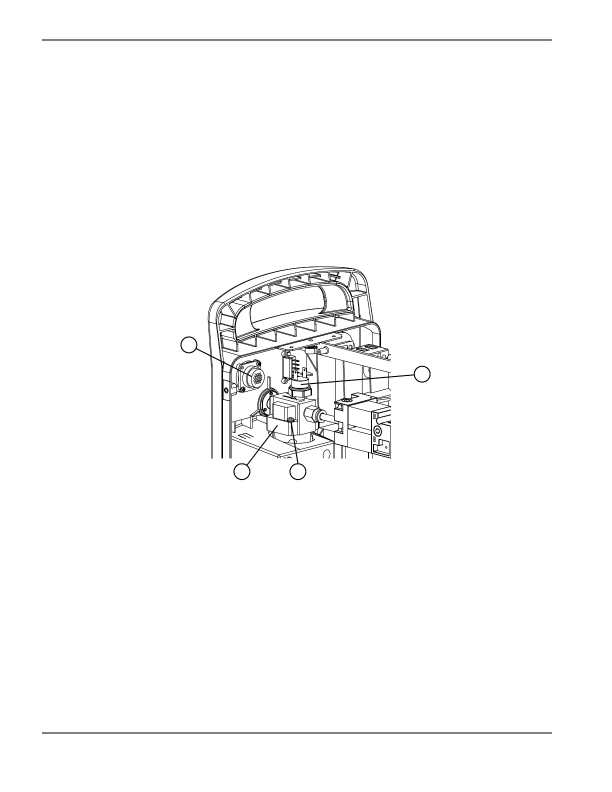
Figure 117
19. Complete the following procedures:
a. See Connect the gas tube on page 189.
b. See Install the end panel bracket on page 175.
c. See Install the component barrier on page 173.
d. See Install the power supply cover on page 172.
e. Reconnect the power and gas supply.
1 CNC interface connector
2 Gas filter assembly
3 Ground wire screw
4 Pressure switch

 Loading...


