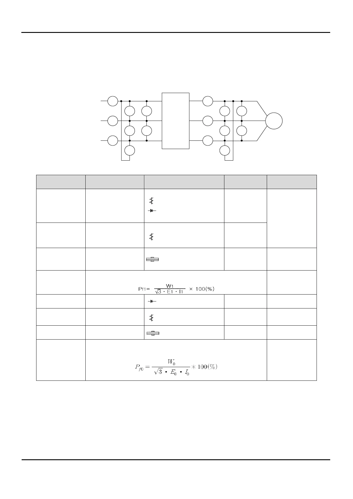
4.3.4 General Inverter Electrical Measurements
The following table specifies how to measure key system electrical parameters.
The diagrams on the next page show inverter-motor systems the location of measurement points
for these parameters.
IR
IS
IT
W11
W12
ES
ER
ET
IU
IV
IW
W01
W02
EV-W
EU-V
EW-U
R
S
T
Power
Supply
U
V
W
R
S
T
U
V
W
I
N
V
E
R
T
E
R
Motor
Circuit location
of measurement
R-S, S-T, T-R
(ER) (ES) (RT)
Moving-coil type
voltmeter or rectifier
type voltmeter
Commercial
supply voltage
(230V class)
200-220V 50Hz
200-240V 60Hz
(460Vclass)
380-415V 50Hz
400-480V 60Hz
R, S, T, Current
(IR) (IS) (IT)
Electronic type
wattmeter
Calculate the output power factor from the output voltage E
1
,
output current I
1
, and output power W
1
U-V, V-W, W-U
(EU) (EV) (EW)
U, V, W Current
(IU) (IV) (IW)
Electronic type
wattmeter
Calculate the output power factor from the output voltage E
0
,
output current I
0
, and output power W
0
Note1: Use a meter indicating a fundamental wave effective value for voltage, and meters indicating total
effective values for current and power.
Note2: The inverter output has a PWM waveform, and low frequencies may cause erroneous readings.
However, the measuring instruments and methods listed above provide comparably accurate
results.
Note3: A general-purpose digital volt meter (DVM) is not usually suitable to measure a PWM waveform
(not pure sinusoid)
 Loading...