EasyManuals Logo

Hyundai N700E User Manual

Hyundai N700E
174 pages
To Next Page IconTo Next Page
To Previous Page IconTo Previous Page
Page #56 background imageLoading...
Page #56 background image
N700E INSTRUCTION MANUAL
2-16
2.1.2.11 Braking Resistor Specification
Resistor values in Table 2-6 are calculated on the basis of 150% rated braking torque, 5% duty
cycle.
Wattage rating of resistor should be doubled for 10% duty cycle. For VFDs greater than 220 HF,
additional braking unit should be installed.
Inverter capacity
Ohm [Ω]
Wattage [W]
055LF/075LFP
17
1000
075LF/110LFP
17
1000
110LF/150LFP
17
1000
150LF/185LFP
8.7
2500
185LF/220LFP
6
3000
220LF
6
4000
055HF/075HFP
70
1200
075HF/110HFP
50
1200
110HF/150HFP
50
2000
150HF/185HFP
30
2500
185HF/220HFP
20
3000
220HF/300HFP
20
4000
Table 2-11: Recommended DB Resistors for the N700E VFDs (5 % Duty Cycle)
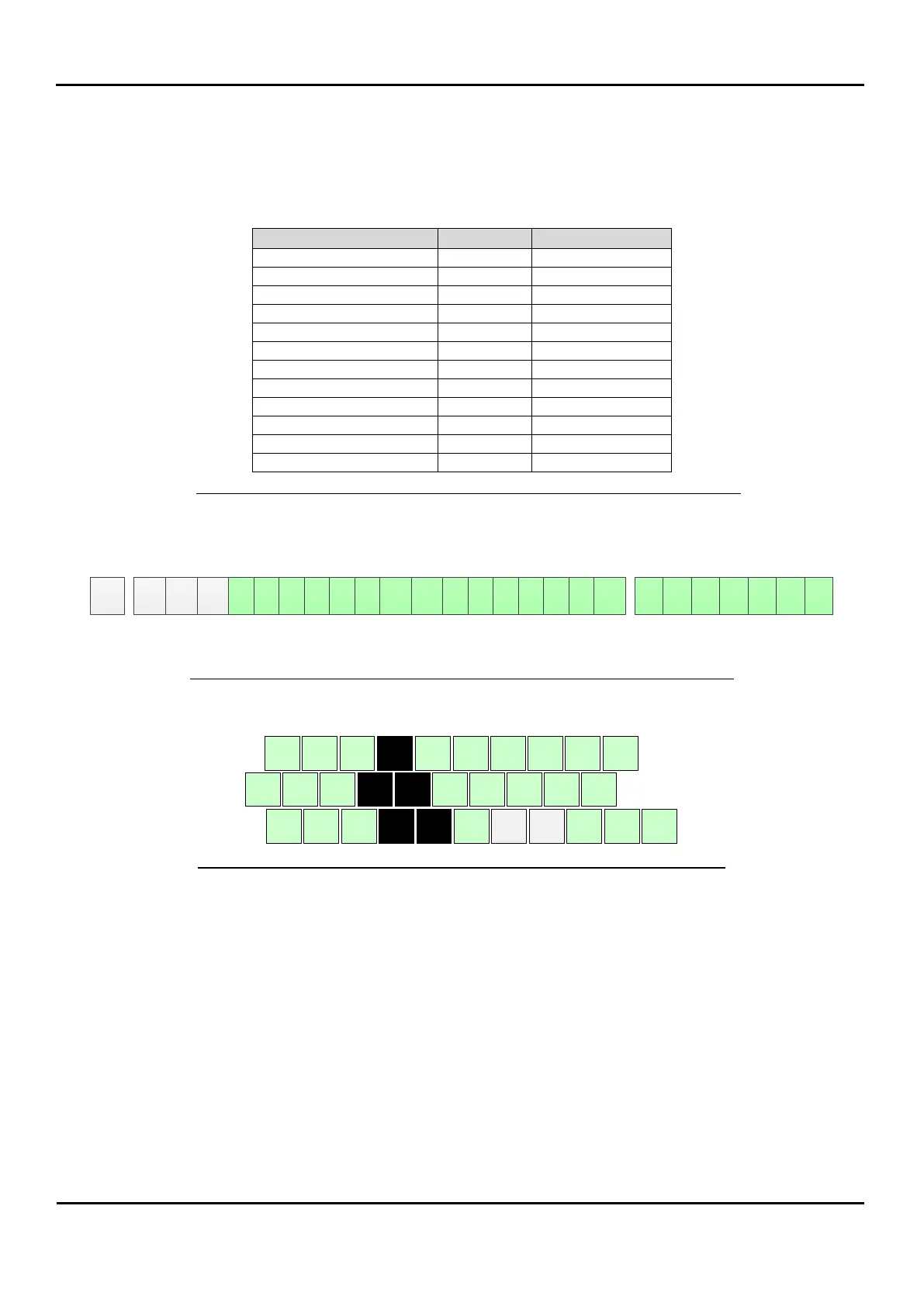
2.1.3 Control Circuit Wiring
RJ45 RXP RNP CM1 6 5 4 3 2 1 CM1 P24 H O OI L L FM AM1 RN0 RN1 RN2 RN3 AL0 AL1 RN2
Figure 2-5: Control Circuit Terminal Connector Diagram (Except 300LF~750LF)
1 3 5 FM AMI OI RN2 RN3
P24 PCS CM L RXP RXN AL0 AL1 AL2
2 4 6 CM H O L RN0 RN1
Figure 2-6: Control Circuit Terminal Connector Diagram (Only 300LF~750LF)

Table of Contents

Questions and Answers:

Question and Answer IconNeed help?

Do you have a question about the Hyundai N700E and is the answer not in the manual?

Hyundai N700E Specifications

General IconGeneral
BrandHyundai
ModelN700E
CategoryInverter
LanguageEnglish

Related product manuals