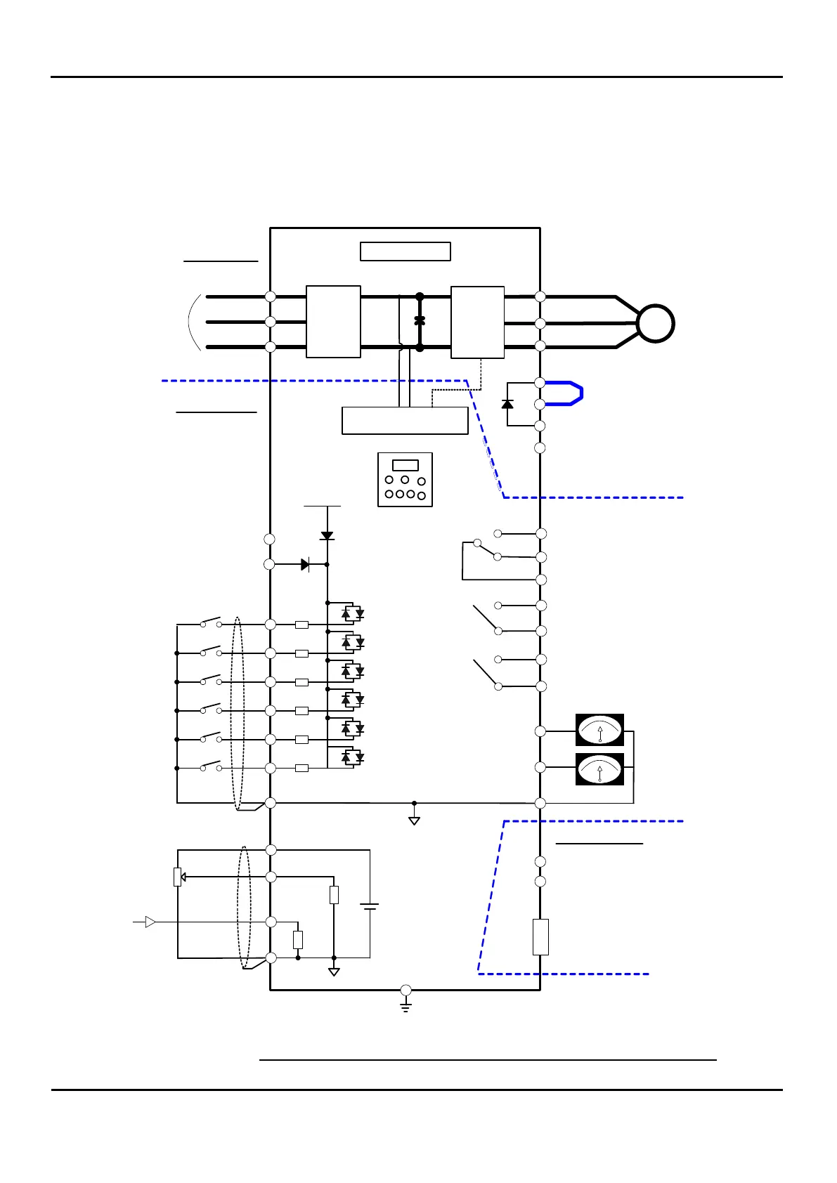
2.1.1 N700E Terminal Connection Diagram and Description
N700E VFD terminal connection overview is shown in Figure 2-1 (Except 300LF~750LF)
There are three segments of Connections
Power Circuit
Control Circuit
Communication
Power Supply 3 Phase
230 V : 200 ~ 240V
460 V : 380 ~ 480 V
(50/60 Hz 10 %)
R
S
T
U
V
W
2
CM
H
O
OI
L
3
Output Monitor
( Analog Voltage Out)
DC 0~10V
DC 4~20mA
Output Relay 1
(
Default: Alarm Signal
)
G
AL1
AL2
AL0
RN3
RN2
(
Default
:
RUN Siganl
)
Control Circuit
N700E
IM
T1
T2
T3
Rectifier
Control PCB
Inverter
Signals
L
Power Circuit
1
Intelligent Input
(
6 connections)
(
Digital Input
)
4
5
6
P10V
RXP
RXN
Analog Input
200
10k
230 V D type
460 V C type
Earth Ground
1~5kΩ
Communication
RN1
RN0
(
Default: Frequency Arrival Signal
)
AMI
Output Monitor
( Analog Current Out)
FM
Output Relay 2
Output Relay 3
Ω
Ω
Short Bar
PD
P
RB : 5.5 KW( HD ) ~ 22KW( HD)
BRD circuit installed for
5.5 to
22kW (7. 5 ~ 30 HP ) Models
N : 30KW( HD ) ~ 350KW( HD)
P24
P24V
CM1
RJ45
Figure 2-1: N700E Terminal Connection Overview (Except 300LF~750LF)
 Loading...