CF2
CF3
CF4
CF1
FW
0
0
0
1
0
0
0
1
A11
A12
A13
A14
A15
A16
A17
A18
A19
A20
A21
A22
A23
A24
A25
F01
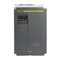
Frequency
0
0
0
0
CF4 CF3 CF2 CF1
0
0
0
0
0
0
0
0
1
1
1
1
1
1
1
1
0
0
0
0
1
1
1
1
0
0
0
0
1
1
1
1
0
0
1
1
0
0
1
1
0
0
1
1
0
0
1
1
0
1
0
1
0
1
0
1
0
1
0
1
0
1
0
1
Frequency
F01
A11
A12
A13
A14
A15
A16
A17
A18
A19
A20
A21
A22
A23
A24
A25
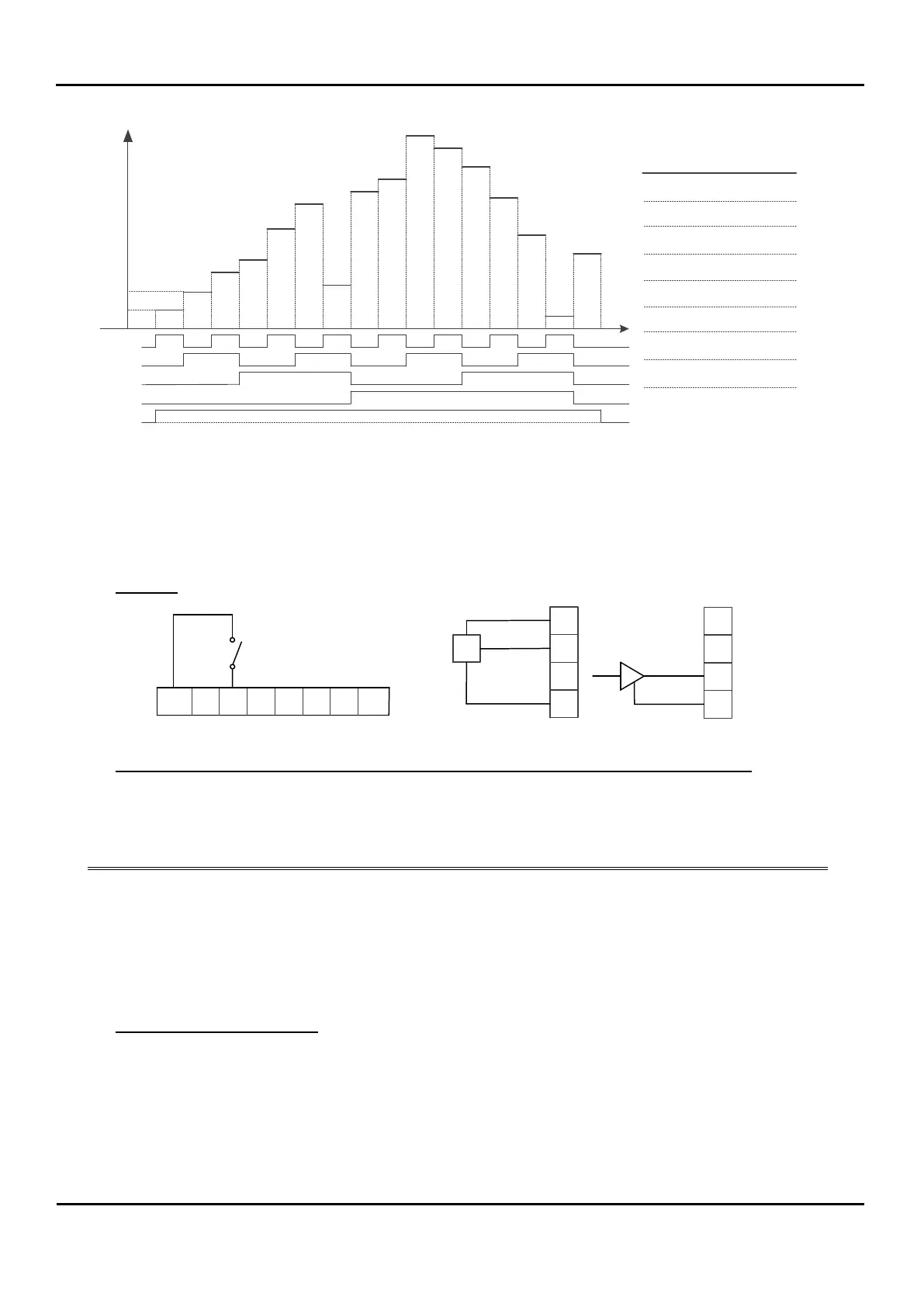
2.3.4 Frequency Command Source to Input Analog Voltage / Analog Current
Input Terminal Diagram
Programming N700E Parameters
Programming Frequency Set Point
Diagram
Programming Frequency Command Source to Input Voltage Source or Current Source
On Keypad, program following parameters with corresponding values
Frequency Command Source to Input Terminal
Set Terminal 5 to AT Operation.
If Closed, Select Current Source. If opened, Voltage Source.
If function 13 is not programmed to any of the terminals on the terminal
strip (C01 ~ C06), frequency setpoint is the sum of current source and
voltage source
Setting Frequency Setpoint
Program following parameters with specified frequency values.
Frequency setpoint follows analog reference (0 ~ 10V / 4 ~ 20 mA) from 0 to 60 Hz. Analog input
settings can be modified using A05 ~ A09.
H
O
OI
L
VR
DC 12V
DC 0~10V
H
O
OI
L
DC 4~20mA
Input Voltage Source
Setup
Input Current Source
Setup
 Loading...