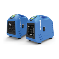
2.1.3.3 Example of Connection to PLC
Figure 2-9: Output Terminal and PLC Connection Diagram
2.1.4 RS 485 Wiring
N700E VFD communication with external controller is done via Modbus over a RS 485 network.
RJ45 modular connector is located on the control terminal strip. In addition, a second RS 485 option is
offered via RXP/RXN terminals.
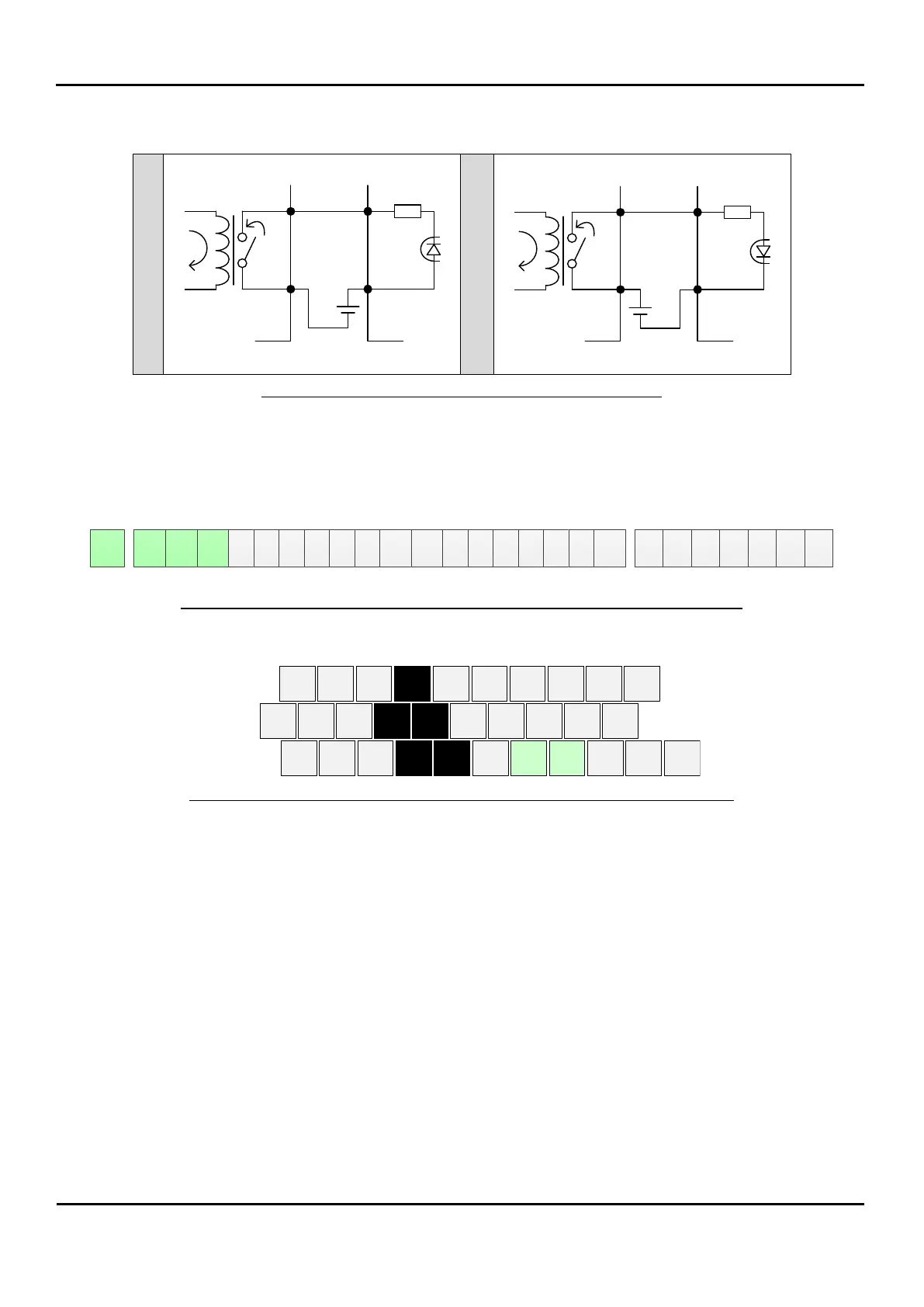
RJ45 RXP RNP CM1 6 5 4 3 2 1 CM1 P24 H O OI L L FM AM1 RN0 RN1 RN2 RN3 AL0 AL1 RN2
Figure 2-10: Communication Terminal Connector Diagram (Except 300LF~750LF)
1 3 5 FM AMI OI RN2 RN3
P24 PCS CM L RXP RXN AL0 AL1 AL2
2 4 6 CM H O L RN0 RN1
Figure 2-11: Communication Terminal Connector Diagram (Only 300LF~750LF)
RN0(RN2)
RN1(RN3)
COM
24V
INVERTER PLC
RN0(RN2)
RN1(RN3)
COM
24V
INVERTER PLC
 Loading...