14 Multi-Wave PE653-PE953 Installation Guide
Copyright © 2010 Intermatic, Inc.
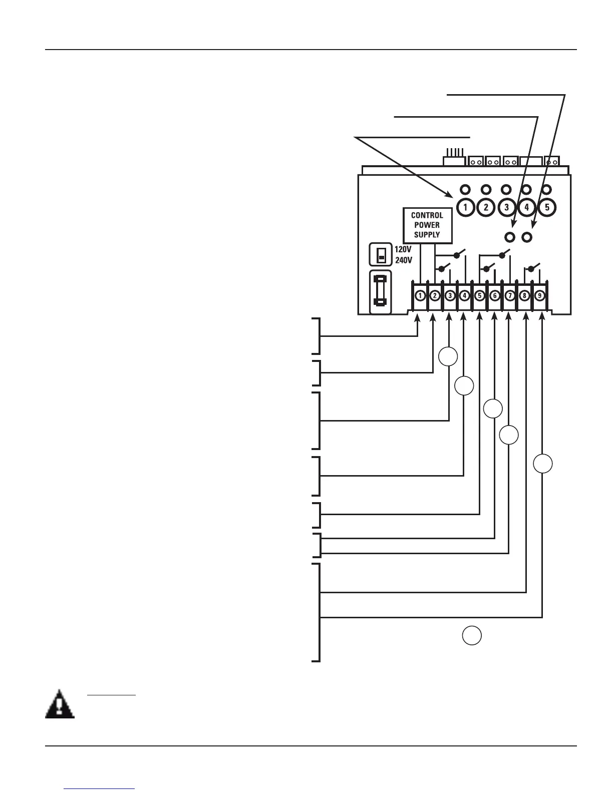
Wiring Instructions
Power Connections
1- Speed Pump: Must be powered from •
Terminal 3.
2-Speed Pump: Must be powered from •
Terminal 3 for High-Speed and Terminal 4 for
Low-Speed.
Booster Pump: Must be powered from •
Terminal 6.
Actuator Control: Must be powered from •
Terminal 7.
Heater Control: Must be Terminals 8 & 9. •
The metal enclosure must be ground bonded •
in compliance with national, state and local
codes.
Terminal 1 must always be Neutral when using
120 VAC power.
Terminal 1 must be L2 when using 240 VAC.
Terminal 2 must always be Hot or L1 for both
120 VAC and 240 VAC.
Terminal 3 must always be connected to the Hot
terminal of the pump.
Terminal 3 must always be connected to the
HIGH SPEED terminal of a 2-speed pump.
Terminal 4 must always be connected to the
LOW SPEED terminal of a 2-speed pump when
using a 2-speed motor.
Terminal 5 is the input supply for both terminals
6 & 7. This terminal is rated at 15 A. maximum.
Terminal 8 is the input supply for terminal 9.
The load is rated at 15 A. maximum.
Terminals 8 & 9 can be used for low voltage
provided the Low Voltage Divider is used to
separate the Low Voltage conductors from Line
Voltage conductors. Low voltage conductors
must exit the cabinet through a separate
opening. (See Figure 3-1)
Terminals 6 & 7 are function selectable with a
maximum combined rating of 15 A.
LOAD 1
LOAD 2
LOAD 3
LOAD 4
LOAD 5
POWER IN & CONTROL
POWER SUPPLY
POWER IN
POWER IN
1
1
2
3
4
5
= Circuit number
Figure 3-2 PE653 Master Control Center Power Terminal identification
CAUTION: The PE653 is a control device and NOT a safety disconnect. A proper sized fused disconnect
or breaker of no more than 125 Amp capacity must be provided in the power supply circuit. Proper
gauge wire should be based on local code requirements of amperage and wire length.
Manual ON/OFF Switches
AC POWER & STATUS indicator
INCLUDE/EXCLUDE switch
 Loading...