Three: PE653 Receiving Device Installation 15
Providing a brighter solution.™
Upper Terminal Connections
Installation Instructions
To avoid fire, shock, or death, turn off power at circuit breaker and test that power is off 1.
before wiring.
Select a location for the installation that is near the pool/spa equipment; at least five (5) feet 2.
distance or more from either the pool or spa and at least five (5) feet above ground level. The
PE653 must be mounted in a vertical (upright) position on the top of the enclosure.
Select the knockouts to be used. Remove the inner 1/2” knockout by inserting a flathead 3.
screw driver in the slot and carefully punch the knockout loose and remove the slug. If a
3/4’ knockout is required, remove the outer ring with pliers after removing the 1/2” knockout.
Smooth the edge with a file if required.
Place the metal enclosure in the desired mounting location and mark the three mounting 4.
holes. Install the top screw first and then hang the enclosure by the keyhole. Then install the
bottom screws, tightening all screws for a secure mounting.
Install electrical conduit as needed to comply with all national and local electrical and safety 5.
codes.
If a low voltage circuit or a heater control circuit is to be used, remove the low voltage 6.
knockout from the PE653 enclosure.
Install electrical conduit as required by national, state and local codes. 7.
Bond the enclosure in accordance with your state and local codes. Where required, 8.
connect a No. 8 AWG solid copper wire to the enclosure using Bonding Lug (part number
156T11047A). Connect the bonding wire to an approved earth ground.
Identify and install all wires necessary to complete the installation. Allow a length of 9.
approximately 18” of each wire at the metal enclosure for required connections of junctions.
Connect wiring for circuits as required. Refer to the diagrams in this section for wiring 10.
suggestions for specific equipment combinations. All splices and wire nut connections
should be in the metal enclosure, not in the PE653 enclosure.
Check and tighten all connections and circuits. 11.
Apply power.12.
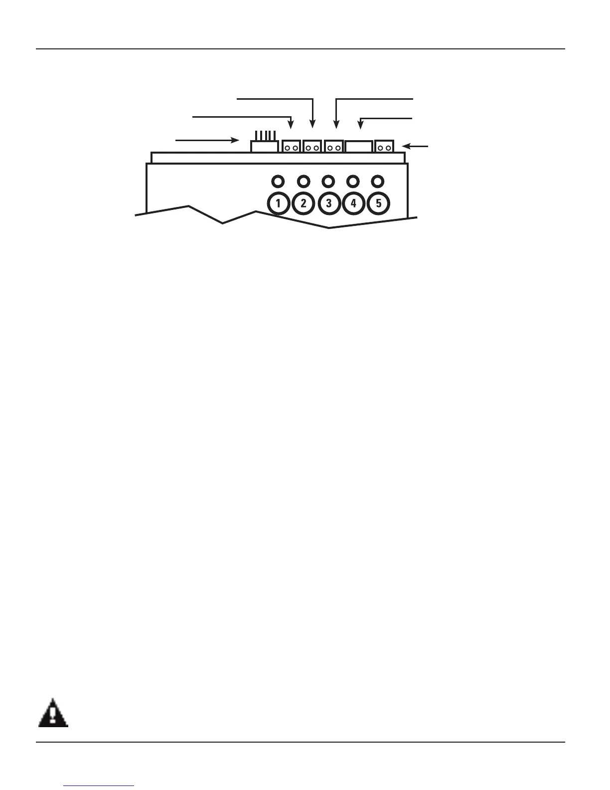
Figure 3-3 PE653 Master Control Center Upper Terminal identification
Local Antenna Connector
Air Sensor (178PA28A)
Water Sensor (PA122)
Solar Sensor (PA122)
Remote Antenna Connector
Serial Connection (RS485)
NOTE: Observe polarity when
connecting pump manufacturer’s
cable to the Serial connection.
THE METAL ENCLOSURE MUST BE CLOSED AND SECURED WITH A LOCK OR TY-WRAP.
 Loading...