38 Multi-Wave PE653-PE953 Installation Guide
Copyright © 2010 Intermatic, Inc.
Locate the Fireman’s switch terminal in the control section of the heater.3.
Remove the factory installed jumper wire.4.
Connect the other ends of the #14 gauge wires from Step #1 to the Fireman’s Switch terminal 5.
bar in place of the factory installed wire loop.
Do not disconnect high limit or pressure switches.6.
Turn the heater thermostat(s) to maximum setting.7.
Turn the heater switch to the ON position.8.
For dual thermostat heaters turn switch to Spa position.
Provide wiring with insulation at least 3/64” thick and having a temperature rating of at least
90°C.
Connection for Raypak Heaters
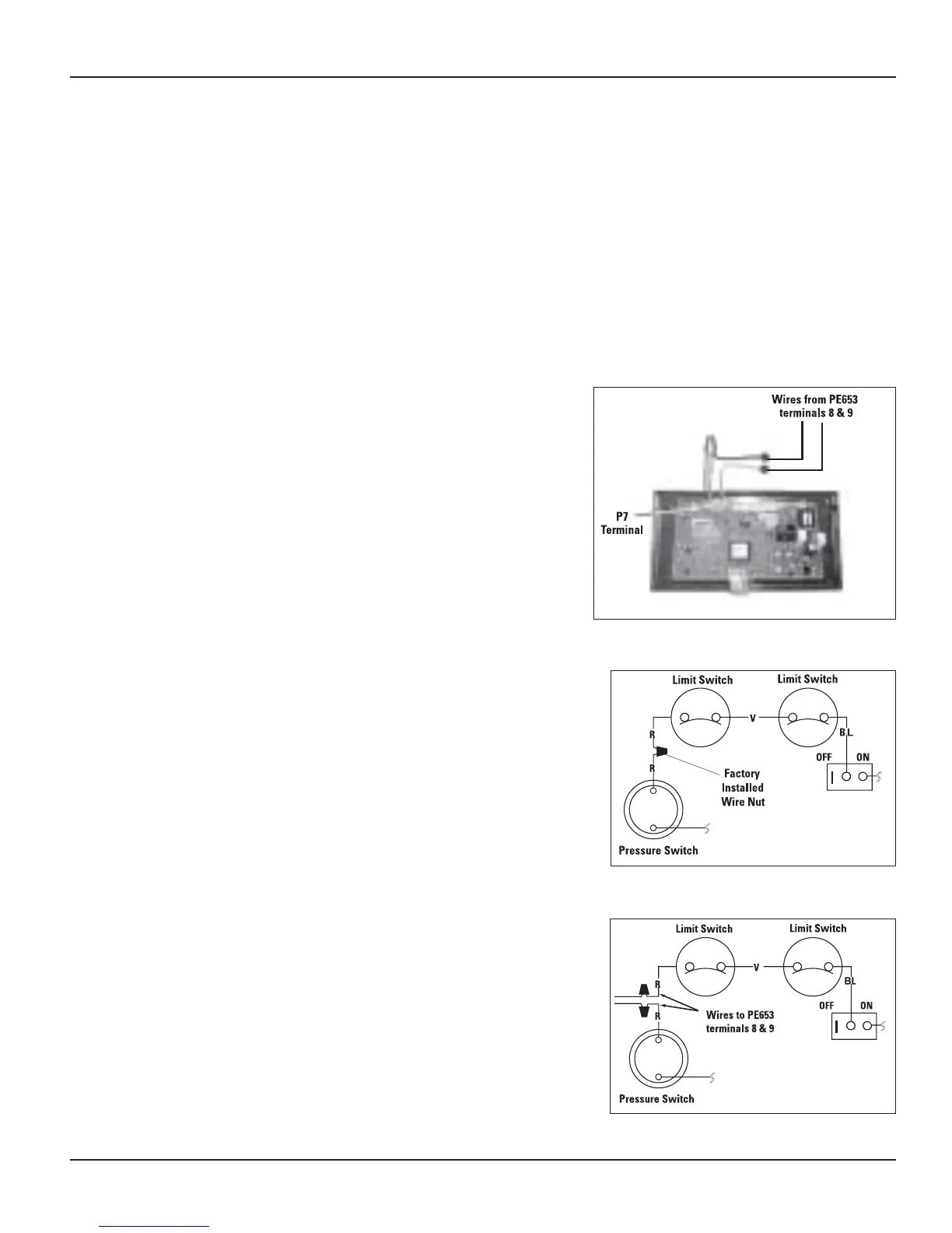
Connect two #14 gauge wires, designed for use in 1.
hot environments, to terminals 8 and 9 in the PE653.
Route the wires through the low voltage knockout in 2.
the PE653 enclosure.
Make sure that the Low Voltage Divider is in place.3.
Connect the orange/black wire and the black/orange 4.
wire to the wire from terminal 8 in the PE653.
Connect the yellow/black wire to the wire from 5.
terminal 9 in the PE653. (see Figure 3-27)
Connection for Hayward Heaters
rs
Connect two #14 gauge wires, designed for use in hot 1.
environments, to terminals 8 and 9 in the PE653.
Route the wires through the low voltage knockout in 2.
the PE653 enclosure.
Make sure that the Low Voltage Divider is in place.3.
Remove heater service door.4.
Remove factory-installed wire nut between two (2) red 5.
wires labeled “CONNECTION FOR FIELD INSTALLED
CONTROL SWITCH” (see Figure 3-28).
Wire nut the two (2) heater wires from PE653 terminals 6.
8 and 9 to the two (2) red wires of the heater (see
Figure 3-29).
Do not disconnect high limit or pressure switches.7.
Set the thermostat selector switch to ON, HIGH, or SPA. 8.
Set the heater thermostat(s) to maximum.9.
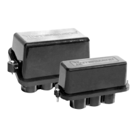
Figure 3-27 — Typical wiring connection for Raypak
Figure 3-28 —
Hayward Heater Wiring Before Modification
Figure 3-29 — Wiring with PE653 Receiving Device

 Loading...