SV-DA200 series AC servo drive Function codes
-116-
3
rd
notch filter→1
st
notch filter
Copy the parameters of 3
rd
notch filter to 1
st
notch filter and then
restore the parameter of 3
rd
notch filter to the default values
4
th
notch filter→2
nd
notch filter
Copy the parameters of 4
th
notch filter to 1
st
notch filter and then
restore the parameter of 4
th
notch filter to the default values
3
rd
and 4
th
notch
filter→1
st
and 2
nd
notch filter
Copy the parameters of 3
rd
and 4
th
notch filter to 1
st
and 2
nd
notch filter and then restore the parameter of 3
rd
and 4
th
notch filter to the default values
1
st
mechanical resonance
frequency
2
nd
mechanical
resonance frequency
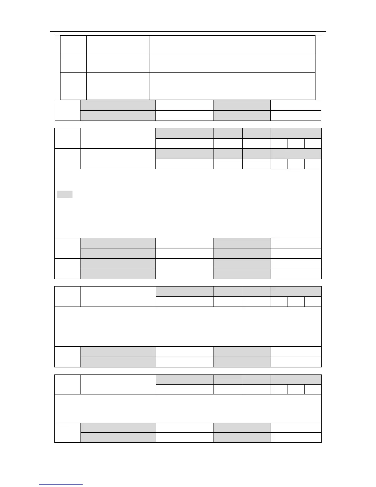
This parameter is used to display the resonance frequency. When P1.20 is set to “1”, the system
will detect the frequency of the max. resonance point and display it by function codes.
Note:
1. Only when the speed reaches above 30r/min will the measuring value be correct.
2. This function is only for read and cannot be set. The user can set the frequency of notch filter
according to the function code to remove the mechanical resonance.
3. 5000 indicates the resonance point is not found.
1
st
notch filter frequency
This parameter is used to set the frequency of 1
st
notch filter for suppressing resonance. The
notch filter can simulate the mechanical resonant frequency and thus suppressing the resonant
frequency.
When this parameter is set to 5000, the function of notch filter will be invalid.
This parameter is used to set the Q value (quality factor) of 1
st
notch filter
Q=Center frequency of 1
st
notch filter/bandwidth of the notch. Generally, this parameter should
remain in default value.
 Loading...
