SV-DA200 series AC servo drive Wiring instruction
-41-
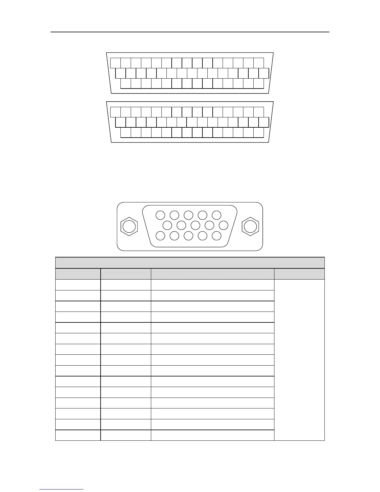
3.4 Control I/O-CN1 terminal layout
CN1 plug pin layout
CN1 plug signal layout
44 43 42 41 40 39 38 37 36 35 34 33 32 31
30 29 28 27 26 25 24 23 22 21 20 19 18 17
15 14 13 12 11 10 9 8 7 6 5 4 3 2
16
1
OA+ OA- OB- OB+ 24V DI4 OCP DI2 OCA GND DI5 SIGN- SIGN+ OCS
OCB DO4 OZ+ OZ- OCZ AO2 PULS-PULS+ DI10 AO1 AD2 GND DI9 DI6
DO2 DO1 DO6 COM- DO3 DI3 DO5 GND AD3 GND GND DI8 DI7 COM+
DI1
AD1
Remark: This is the interface definition for standard model; refer to chapter 4 for terminal
function and application. See corresponding operation guide for EtherCAT bus type.
3.5 Wiring of encoder-CN2 terminals
3.5.1 CN2 terminals
5 4 3 2 1
10 9 8 7 6
15 14 13 12 11
Parallel encoder V+/Serial encoder data+
Different
encoders use
different
cables
Signal of parallel encoder W+
Signal of parallel encoder A+
Signal of parallel encoder A-
Signal of parallel encoder U+
Parallel encoder V-/Serial encoder data-
Signal of parallel encoder W-
Signal of parallel encoder B-
Signal of parallel encoder B+
Signal of parallel encoder U-
Signal of parallel encoder Z-
Signal of parallel encoder Z+
 Loading...
