Note:
1. PROFIBUS-DP communication card provides two rotary switches (S3, S4) to set the
communication address on PROFIBUS-DP network. These two rotary switches of binary are used to
set the ones and tens of the communication address. The valid range of the communication address
is 0–99. The address modification will be effective immediately, it is recommended to set
PROFIBUS-DP address during power-off to prevent accidents.
2. It is necessary to use 150Ω twisted pair cables according to the electric transmission mode of
EIA-485 standards.
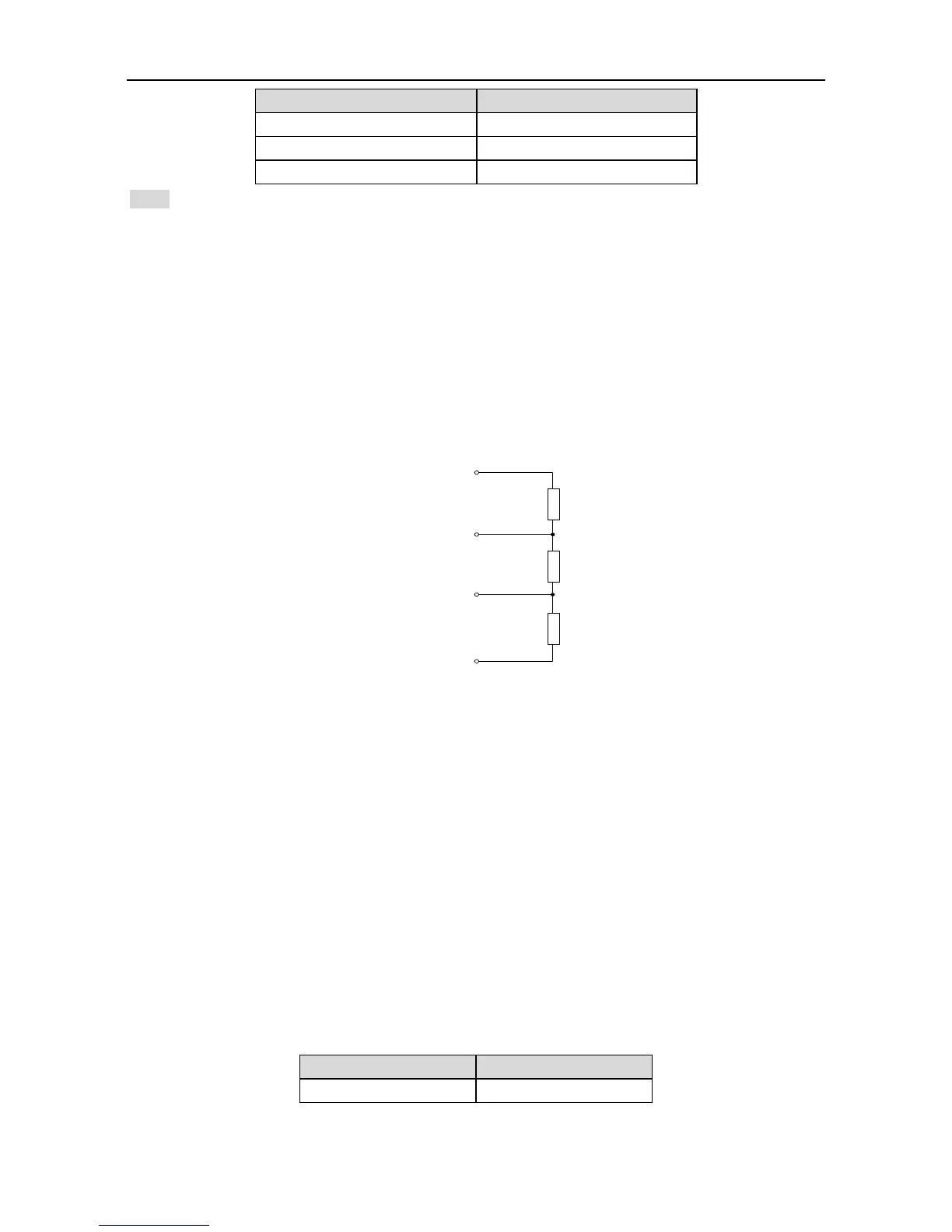
3. It is necessary to add the terminal resistor to the start terminal and end terminal in the same one
PROFIBUS-DP network, the connection mode of the terminal resistor is shown below:
4. The bus transmission baud rate can be identified automatically after the power on of
PROFIBUS-DP communication card.
8.4.3 PROFIBUS-DP software configuration
“Master-slave” mode is available between the data transmission between the main control module
and slave control module and SV-DA200 servo drive is always the slave. In real-time control, the
cycle data is used for the command setting and state monitoring and the non-cycle communication
function is used for the diagnosis and troubleshooting of the data transmission.
The drive control needs parameter and process data. The non-cycle data is used to control
commands and drives. The process data is cycle data for servo drive control. SV-DA200 only
supports PROFIBUS-DP V0 protocol version (support PKW+PZD mode) and PPO type 5. DP-V0 is
the basic communication protocol version and only supports cycle data exchange (MS0
communication). It has the basic configuration for parameters definition and diagnose.
PROFIBUS cycle transmission message applies 32 Byte transmission modes and the data format is
as below:
 Loading...
