EasyManuals Logo
Home>INVT>Controller>SV-DA200-0R7-2

INVT SV-DA200-0R7-2 User Manual

INVT SV-DA200-0R7-2
300 pages
To Next Page IconTo Next Page
To Previous Page IconTo Previous Page
Page #56 background imageLoading...
Page #56 background image
SV-DA200 series AC servo drive Control mode applications
-52-
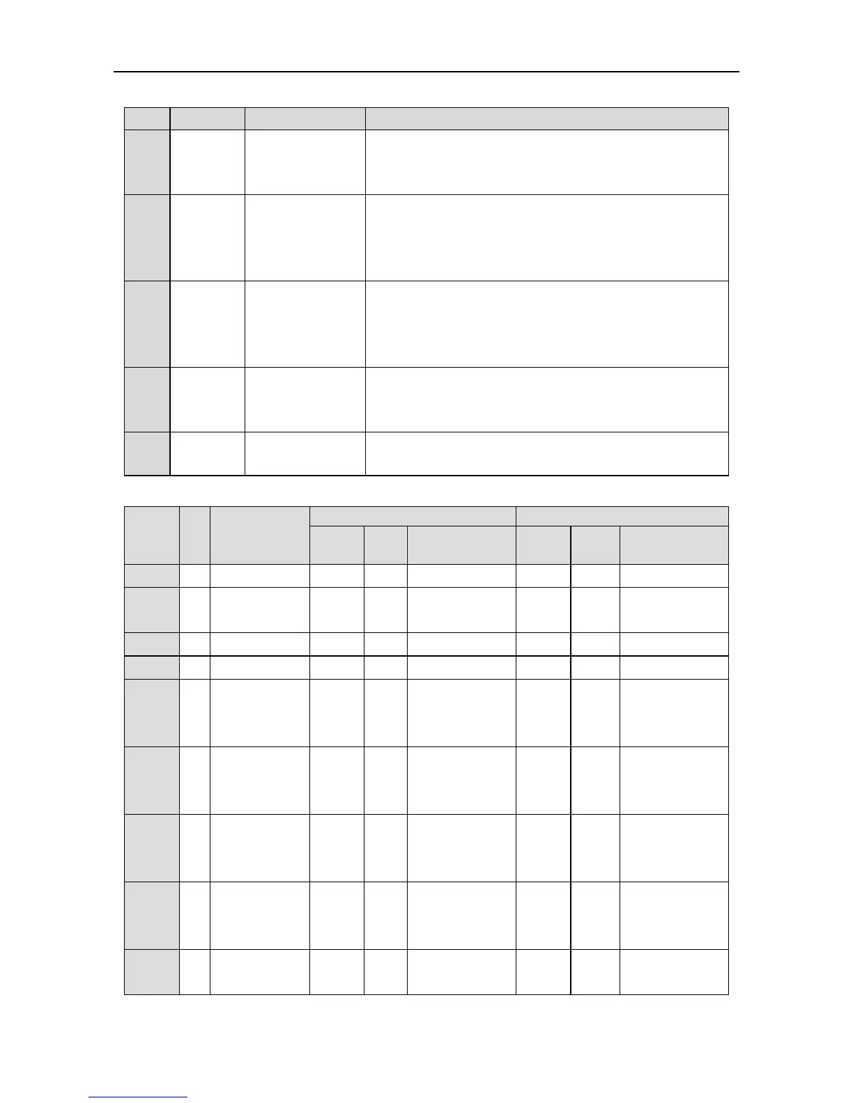
4.4.3 Power supply signal
Sign
Pin no.
Name
Function
24V
40
Internal 24V
power supply
COM- is the ground terminal of the 24V power. Its capacity
is 100mA. If the actual load is higher than this value, the
user shall provide the power supply by themselves.
GND
5, 6, 8, 19,
35
Signal ground
The ground of the internal power supply (except the 24V
power supply) of the servo drive, it is also the ground of
the phase A/B/Z open-collector signal of the encoder and
the analog output signal. It is isolated from COM-.
COM+
2
DI input common
port
If DI is active-low (0V), COM+ connects to internal
24V power (pin 40) or external DC power (12V24V);
If DI is active-high (12V24V), COM+ connects to the
reference ground of corresponding signal.
COM-
12
DO output
common ground
Local 24V power ground
If external DC power 12V24V is used, power 0V is
connected to this terminal.
FG
Enclosure
Enclosure ground
The enclosure of CN1 terminal is connected with the
enclosure of the drive
4.4.4 Configuration table for different digital modes
Symbol
Pin
no.
Name
Position mode
Speed mode
Default
value
Mark
Function name
Default
value
Mark
Function name
DI1
16
Digital input 1
0x003
SON
Servo enabling
0x003
SON
Servo enabling
DI2
37
Digital input 2
0x00D
ZRS
Zero speed
clamp
0x00D
ZRS
Zero speed
clamp
DI3
10
Digital input 3
0x004
CLA
Alarm clearing
0x004
CLA
Alarm clearing
DI4
39
Digital input 4
0x016
EMG
Emergency stop
0x016
EMG
Emergency stop
DI5
34
Digital input 5
0x019
SC1
Molecule 1 of
electric gear
ratio
0x00A
SPD1
Internal speed
command 1
DI6
17
Digital input 6
0x01A
SC2
Molecule 2 of
electric gear
ratio
0x00B
SPD2
Internal speed
command 2
DI7
3
Digital input 7
0x001
POT
Positive
direction drive
disabled
0x001
POT
Positive
direction drive
disabled
DI8
4
Digital input 8
0x002
NOT
Negative
direction drive
disabled
0x002
NOT
Negative
direction drive
disabled
DI9
18
Digital input 9
0x007
RPC
Retention pulse
clearing
0x00E
S-SIG
N
Speed
command sign

Table of Contents

Questions and Answers:

Question and Answer IconNeed help?

Do you have a question about the INVT SV-DA200-0R7-2 and is the answer not in the manual?

INVT SV-DA200-0R7-2 Specifications

General IconGeneral
BrandINVT
ModelSV-DA200-0R7-2
CategoryController
LanguageEnglish

Related product manuals