SV-DA200 series AC servo drive Control mode applications
-69-
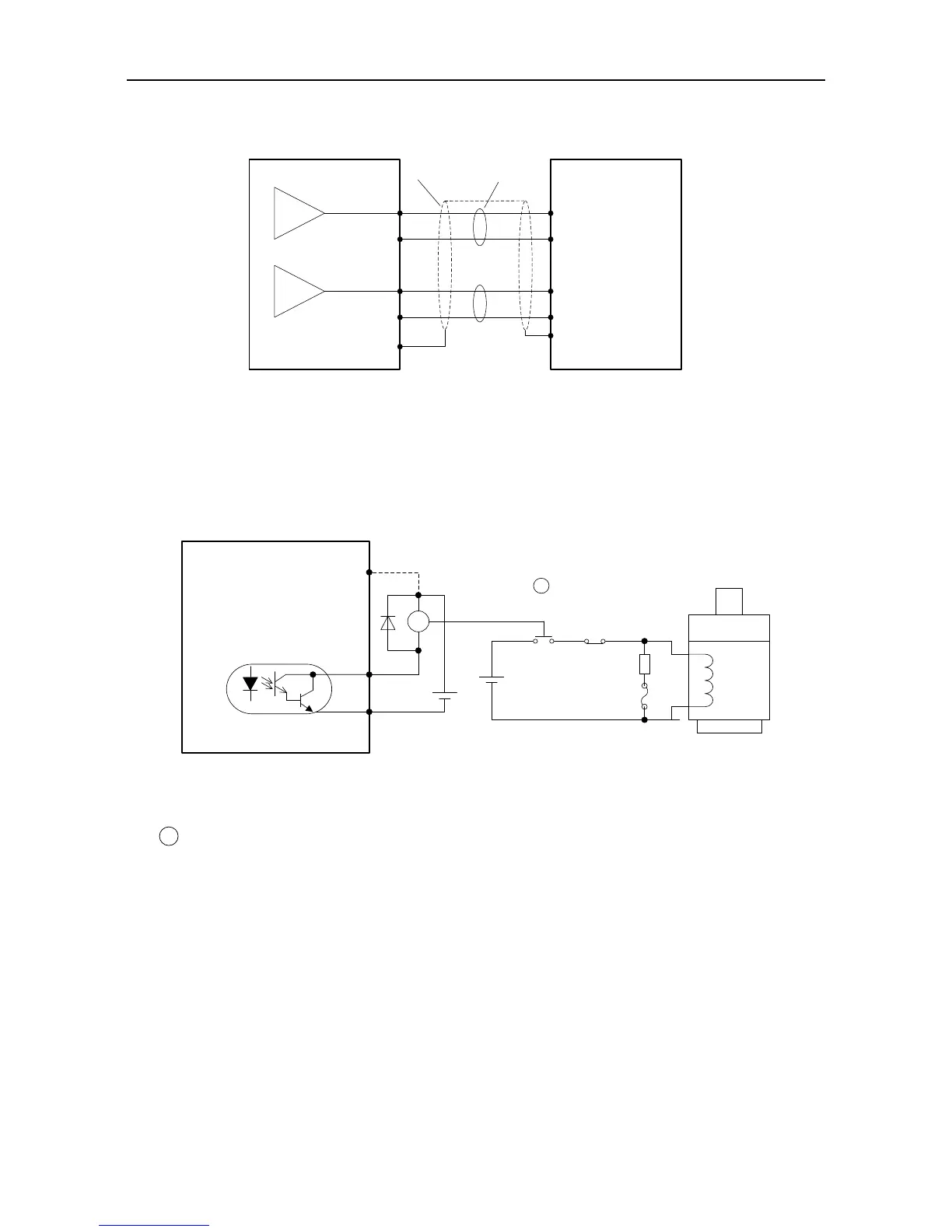
4.5.6 Wiring of the analog output circuit
AO1 21
AO2 25
GND 5
GND 5
GND
GND
AI1
AI2
FG
Measuring instruments or
external circuit
Shield cable
Twisted pair
Connect the shield cable
according to the
requirement
Servo drive
There are two analog output circuits in all. The output voltage range is -10V–10V. The Max
output current is 3mA.
4.5.7 Wiring of the electromagnetic brake
If the servo drive is used in the vertical shaft applications, the electromagnetic brake can be used to
stop and keep the dropping speed when servo drive is power off. The wiring diagram is:
DC12~24V
external power
COM- 12
BRK 9
Connect the dotted lines in
the diagram when local 24V
power is used, and remove
the external power.
Motor
Brake
winding
Surge
absorber
Fuse (5A)
E-stop button
RY
DC24V
power
specific for
brake winding
24V 40
Note: Brake winding must use specific 24V power,
and it cannot be used in common with control power
or relay coil power.
+
-
+
-
Drive side
RY
RY
24V power supply specific for the electromagnetic brake cannot be used with the power supply for
control signal;
is the relay coil, please pay attention to the direction of the diode;
The electromagnetic brake is used to keep the speed, other than stop;
Please install the external braking devices besides the electromagnetic brake.
 Loading...
