SV-DA200 series AC servo drive Commissioning
-229-
gain is too large, it may cause system oscillation.
6) Frequency division of the feedback pulse output
If the feedback pulse needs to be outputted, the frequency division coefficient of pulse output (P0.06,
P0.07) can be used to change the frequency of the output pulse.
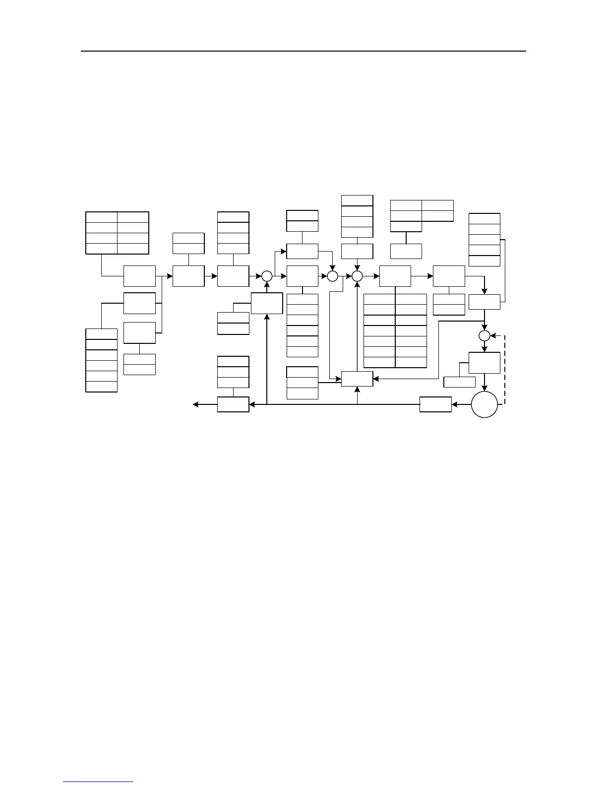
7.2.2 Gain adjustment of speed mode
The speed control block diagram of the SV-DA200 series servo drive is shown in the figure below.
The gain parameters that can be adjusted in the speed mode are marked on the block diagram.
The general procedures for parameter adjustment in the speed mode are:
1) Initial setting of the parameters
The defaults of the parameters can be recovered by the default parameter recovering operation (see
chapter 5.2.5.3 for details).
2) Adjustment of the gain of the speed loop
When the servo motor is running with default parameters, if the system oscillation occurs with buzz,
the speed gain (P2.00, P2.05) should be adjusted smaller. If the system rigidity is relatively small or
the speed fluctuates largely, the speed gain should be adjusted larger.
3) Adjustment of the speed integration time constant
When the gain of the speed loop is increased, the speed integration time constant (P2.01, P2.06)
should be increased at the same time. Similarly, when the gain of the speed loop is decreased, the
speed integration time constant should be decreased at the same time.
4) Adjustment of the ACC/DEC time
If the speed varies violently during starting, it may cause large impulse or even overcurrent. At this
time we adjust the ACC time (P0.54) to smoothen the speed rise. Similarly, we can adjust the DEC
 Loading...
