SV-DA200 series AC servo drive Control mode applications
-65-
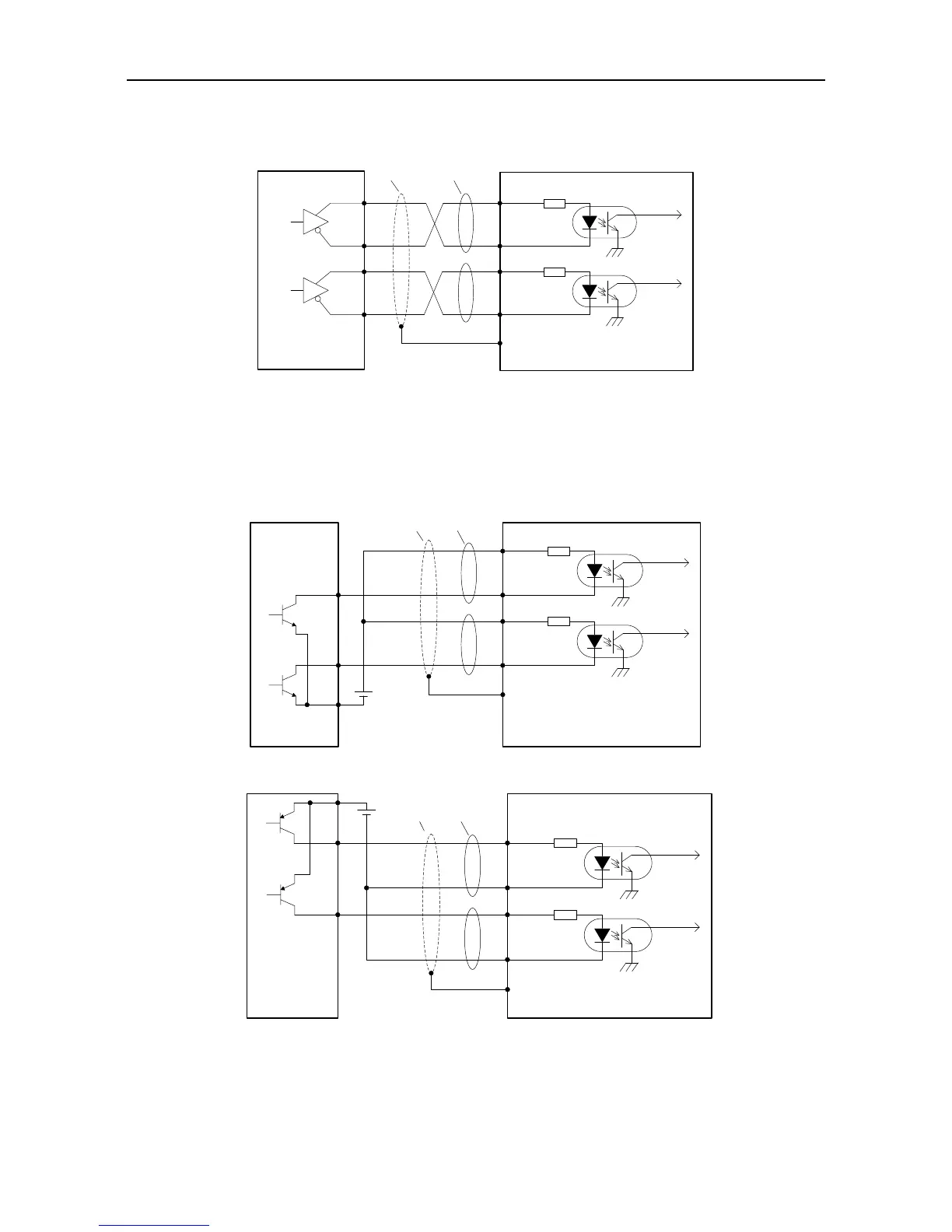
4.5.2 Wiring of the pulse input circuit
Connect mode 1: Differential mode
Control module side
Shielded
cable
Drive side
23 PULS+
24 PULS-
33 SIGN-
FG
PULS
SIGN
32 SIGN+
Twisted
pair
The maximum frequency of input pulse is 4MHz and the input signal voltage is ±5V;
With the best anti-noise capability, this signal transmit method is recommended as the preferred.
Connection mode 2: Open collector mode 1
The control module is NPN (common cathode)
Control module
side
Drive side
38 OCP
24 PULS-
33 SIGN-
FG
Y1
Y0
PULS
SIGN
31 OCS
+
-
Shielded
cable
Twisted
pair
DC24V
The control module is PNP module (common anode):
Control module
side
Drive side
38 OCP
24 PULS-
33 SIGN-
FG
Y1
Y0
PULS
SIGN
31 OCS
+
-
Shielded
cable
Twisted
pair
DC24V
The max. input pulse frequency is 200kHz; if the local 24V power supply (it only can provide
100mA current) or the 24V power supply provided by the user is used, there is no need to
connect to current limit resistor. Generally, most of Japanese PLC is NPN module, while most of
 Loading...
