· Input voltage range of 400V system:
AC 380V(-15%)~440V(+10%)
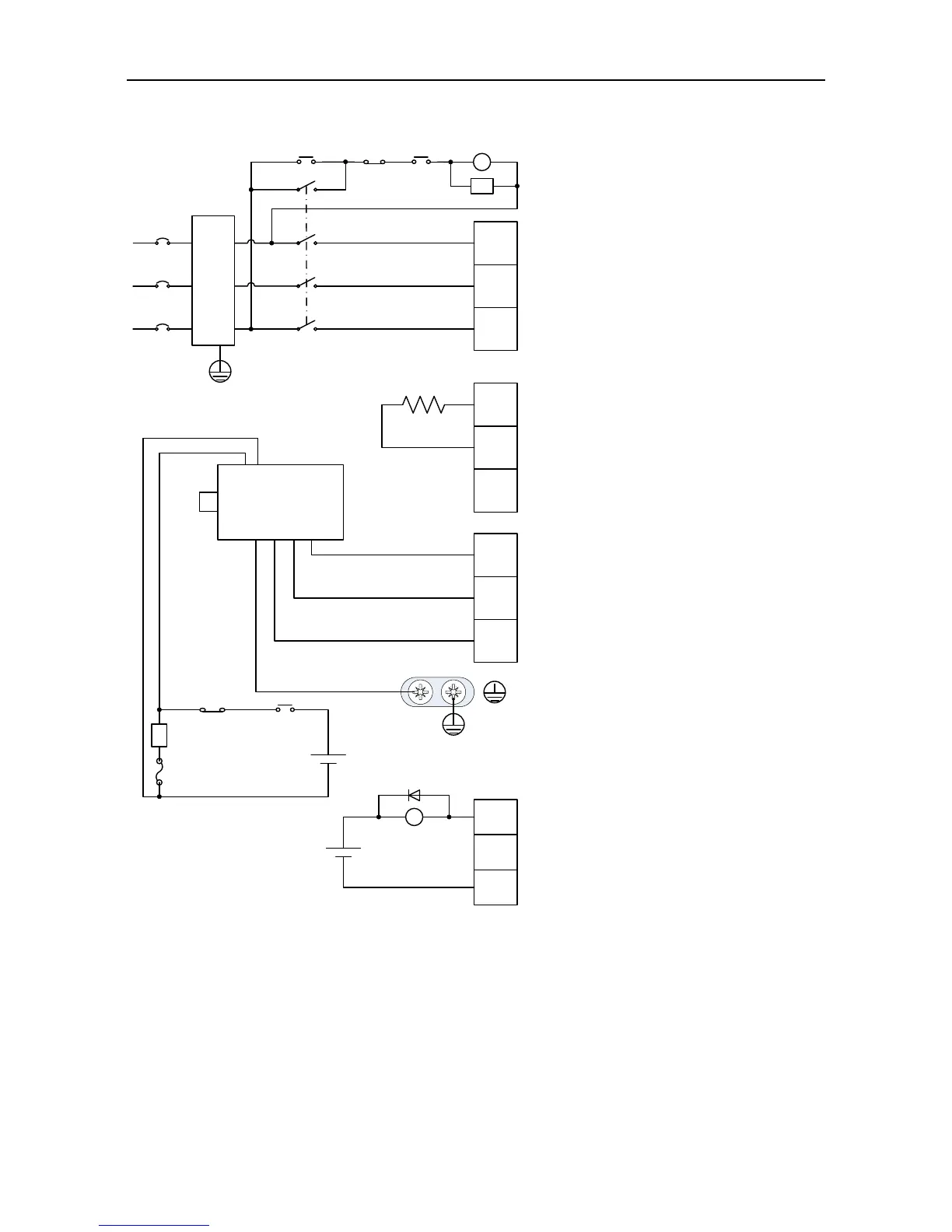
· It is necessary to connect external
regenerative brake resistor between
terminal (+) and PB
· Be sure to ground the servo drive to
avoid accident of electrical shock.
· The electromagnetic brake uses 24V
power supply which should be
provided by the user. Moreover, it
must be isolated from the DC12-24V
power supply which is used by the
control signal.
· Pay attention to the connection of the
freewheeling diode. Reversed
polarity may damage the drive.
· The user is required to make this
emergency stop protection circuit.
· Add surge absorbing devices on both
ends of the electromagnetic
contactor winding.
Fuse
Breaker
MC
MC
RY
DC 24V
(±10%)
OFF
ALM
ON
+
-
R
S
T
(+)
PB
(-)
U
V
W
· Connect output U, V and W to the
drive according to the motor cable
phase sequence of servo motor,
wrong phase sequence will cause
drive fault
Motor
ALM
CN1
+
-
COM-
ALM
Green/Yellow
Emergency
stop button
Surge absorber
EMI
filter
DC 12~24V
(±10%)
 Loading...
