3
ANTRIEBSTECHNIK
6
33
KEB COMBIVERT F4-C
Name: Basis
28.01.98
6
Section
Page
Date
© KEB Antriebstechnik, 1997
All Rights reserved
Chapter
Functional DescriptionDigital In- and Outputs
4 5 6 7 10 11 13 14 19 20
I1 I2 I3 I4 F R 0V U
ext
ST RST
PE
X1
4 5 6 7 10 11 13 14 19 20
I1 I2 I3 I4 F R 0V Uext ST RST
PE
X1
-
+
13...30V DC
Internal power supply
External power supply
6.3.1 Short Description
Digital Inputs
6.3 Digital In- and Outputs
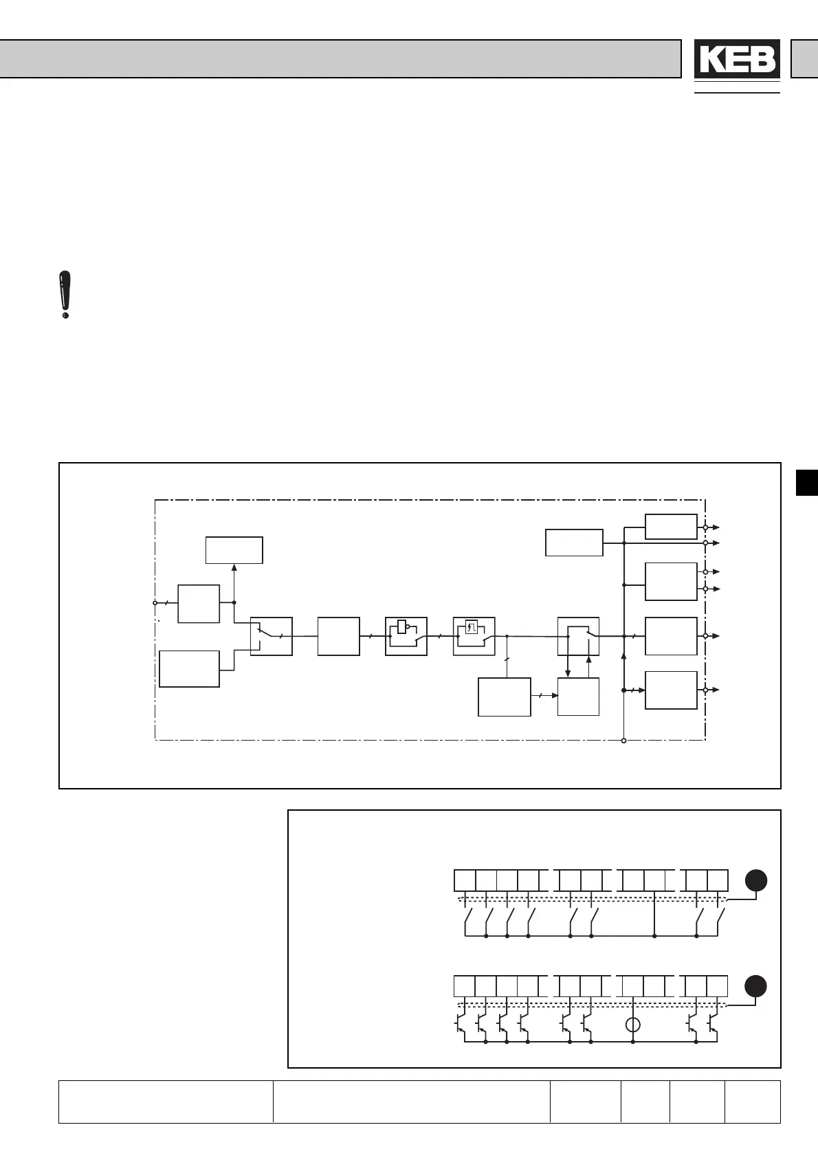
Der KEB COMBIVERT has 8 external digital inputs. Four of them are programmable
(I1...I4). Additionally the KEB COMBIVERT has four internal digital inputs (IA...ID)
They are directly connected with the internal outputs.
Coming from the terminal strip, parameter dr.1 defines PNP-or NPN input logic..
Parameter ru.14 shows the actual active terminals. Every input can be set via the
terminal strip (di.15) or by software with di.16. A digital filter (di.0) reduces the
interference susceptibility of the inputs. With di.2 the inputs can be inverted, or with
di.14 the inputs can be set on edge triggering. A strobe mode can be activated with
parameters di.17...di.19. The input status (ru.16) indicates the inputs that are actually
set for processing. The inputs forward (F) and revers (R) can be changed to run/
stop and forward/revers with di.20. The function of a programmable input is defined
with di.3...di.6. The internal inputs are directly controlled by the internal outputs.
Their function is defined with di.7...di.10.
Picture 6.3.1 Principle of the digital inputs
6.3.2 Input Signals PNP /
NPN (di.1)
Picture 6.3.2.a Digital Inputs in PNP-Control (di.1 = 0)
For safety reasons the control
release (ST) must generally be
operated by hardware. Edge
triggering and strobe signal can
be adjusted, but they have no
influence.
8
di.1
di.16
di.15
8
di.0 di.2
1
di.14
8 8
di.17
di.19
di.18
8
1
ru.14
ru.16
4
4
di.21
PNP/
NPN
Digital
Input
select
Digital
Filter
Strobe
Mode
Strobe-
Input
select
Terminal
state
Internal
Input state
Function
I1...I4
select
di.3...di.6
Function
IA...ID
select
di.7...di.10
Outputs
Out A...Out D
ST-int
RST-int
F-int
R-int
I1...I4-int
IA...ID-int
Terminal strip X1
F / R
or
Run/Stop
di.20
Reset-
Mode
U
in
= 13...30V DC
±0% smoothed
R
i
= 4,4kΩ
 Loading...


