6 11
KEB COMBIVERT F4-C
6
Name: Basis
30.01.98
Functional Description PI-Controller
© KEB Antriebstechnik, 1997
All Rights reserved
Chapter Section Page
Date
cn.0 Bit 1 and 2 = „3“
Set value
Actual value
PI-Controller
Speed detection
f
Presetting
+
+
f_out
This setting requires the optional available speed detection card (see Chap. 6.9) to
record the actual value. Speed controls with incremental encoder, tacho generator or
pulse encoder can be set up.
At high load torques autoboost causes an automatic I•R compensation by increasing
the output voltage; the magnetizing current remains constant. The slip compensation
compensates the speed changes caused by load changes.
The combination of both functions improves the performance over the entire speed
range. During regenerative operation, only with positive voltage change, a smoother
braking behaviour is adjusted with autoboost (cn.0 bit 7).
1. Enter motor data (Cahpter 6.6)
2. Activate autoboost and slip compensation (see cn.0)
3. Adjust parameter cn.1 and cn.2 to „0.00“
4. Measure the speed on idling machine. Put a load on the machine and repeat
the measurement. If nesessary, adjust parameters cn.1 and cn.2 to the desired
speed/torque performance characteristic.
5. Take the load off the machine. Check, whether voltage and frequency are
reduced again.
6.11.3 Autoboost and
Slip
Compensation
f
n
Mot
f
n
Mot
f
n
Mot
f
n
Mot
d
c
b
a
f / n
Mot
t
=
=
=
=
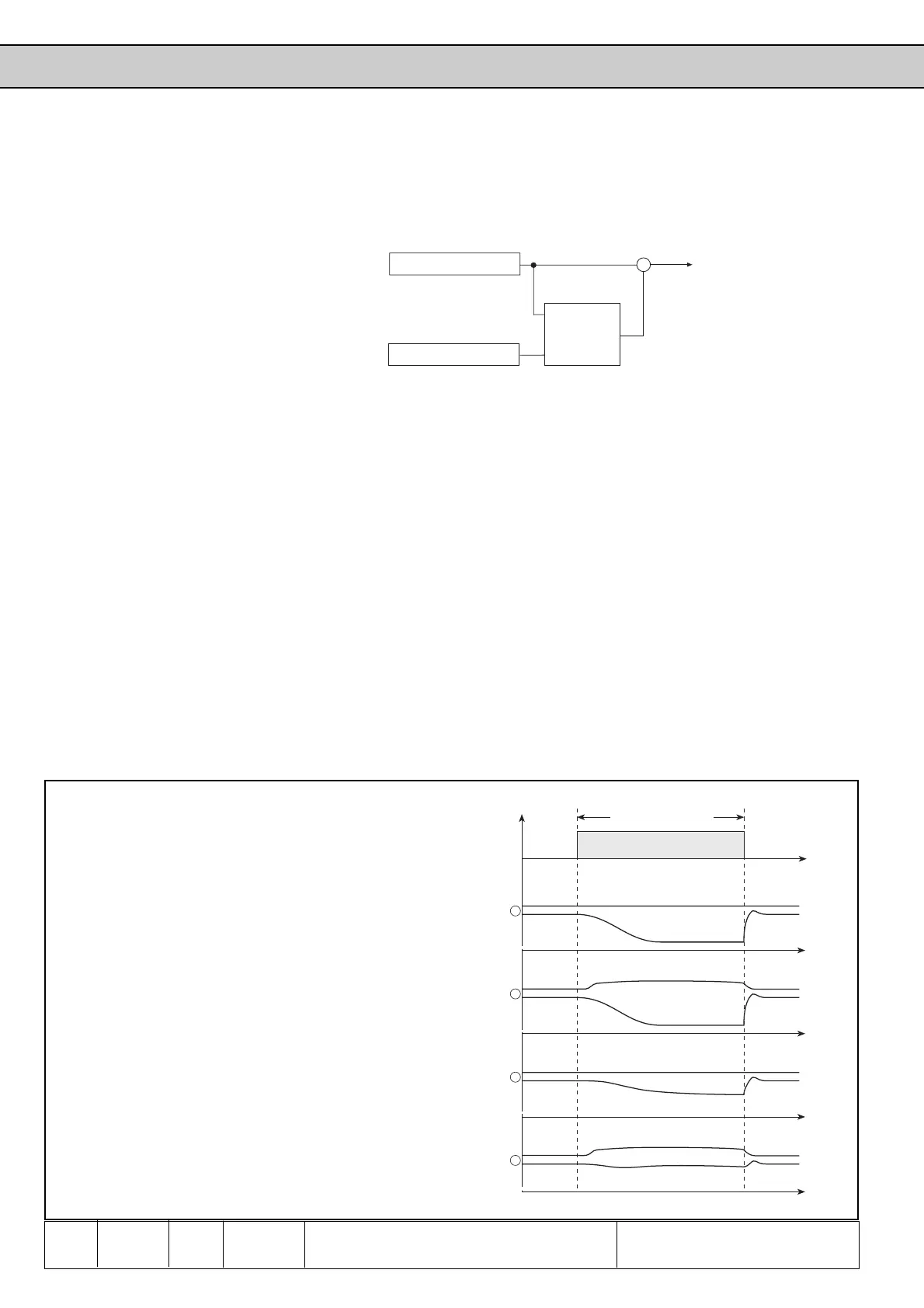
a) No frequency rise, speed decays => no controller
activated or adjusted too low.
b) Frequency is increased, speed decays => voltage
rise too little or not existing.
c) No frequency rise, speed decays => frequency rise
too little or not existing.
d) Speed is maintained after a short adjustment phase
=> optimal setting.
Picture 6.11.3 Autoboost and slip compensation
Load
 Loading...


