5
ANTRIEBSTECHNIK
4
35
KEB COMBIVERT F4-C
Name: Basis
20.03.98
4
CP - Parameter
© KEB Antriebstechnik, 1997
All Rights reserved
Operation
Chapter
Section
Page
Date
Display of actual inverter load in percent. 100% load correspond to the rated inverter
current. Only positive values are displayed, i.e. no difference is made between motoric
and regenerative operation.
This indication permits the recording of short-time load peaks, by storing the highest
value that occurred. The display value is in percent (100% = rated inverter current).
The peak value can be reset with ▲ or ▼ at running unit, or by switching off the unit
from mains.
Actual load
Peak load
4.3.5 Basic Setting of
the Drive
The following parameters determine fundamental operating data. They should be
checked in any case and, if necessary, adapted to the application.
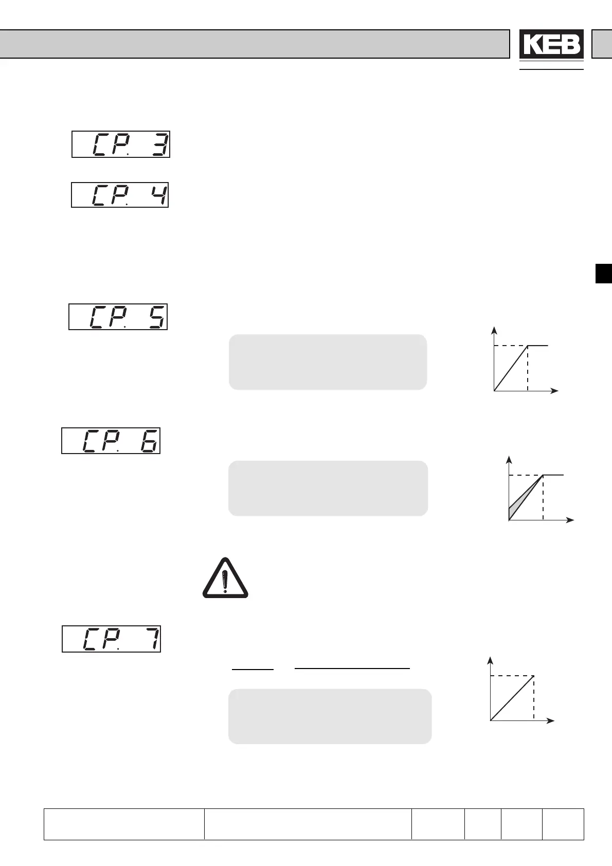
At the frequency adjusted here the inverter reaches its maximum output voltage. The
input of the rated motor frequency is typical in this case. Note: Motors may overheat
with a wrongly adjusted rated frequency!
Setting range: 0...409,58 Hz
Resolution: 0,0125 Hz
Factory setting: 50,0 Hz
Customer setting: _______ Hz
Rated frequency
Boost
Acceleration time
In the lower speed range a major part of the motor voltage drops across the stator
resitance. To maintain a nearly constant breakdown torque of the motor over the
entire speed range, the voltage drop can be compensated by the boost.
Setting range: 0...25,5 %
Resolution: 0,1 %
Factory setting: 2,0 %
Customer setting: _______ %
Setting: - Determine load during idling at rated frequency
- Preselect approx. 10Hz and adjust the boost, so that about the
same load as with rated frequency is reached.
If a motor is continously driven at low speed with overvoltage, it can lead
to overheating of the motor.
The parameter determines the time required to accelerate from 0 to 100 Hz.The real
acceleration time is proportional to the frequency change.
delta f real acceleration time
=
100 Hz CP.7
Setting range: 0,01...300 s
Resolution: 0,01 s
Factory setting: 10 s
Customer setting: _______ s
Example: CP. 7 = 10 s ; the drive shall accelerate from 10 Hz to 60 Hz
delta f = 60 Hz - 10 Hz = 50 Hz
real acceleration time = (50 Hz / 100 Hz) x 10s = 5 s
U
A
f
100%
CP. 5
U
A
f
CP. 6
CP. 5
f
t
100 Hz
CP. 7
 Loading...


