3 1
KEB COMBIVERT F4-C
6
Name: Basis
09.02.98
Chapter Section
Page Date
© KEB Antriebsteclnik, 1997
All Rights reserved
Hardware Control Cards
20 22 23
1234
21
16 17 1856789101112131415 19
123456789101112
13 14 15 16 17 18 19 20 21 22 23
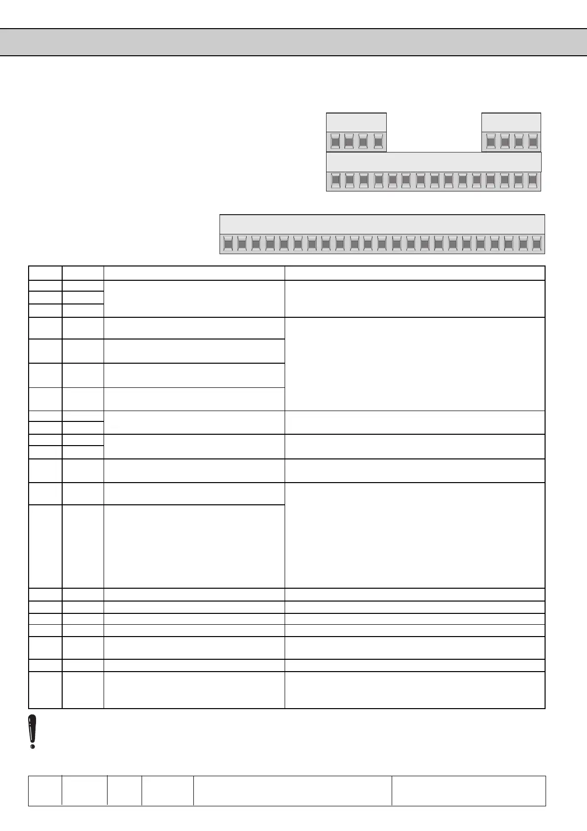
3.1.5 Control Terminal
Strip
for housing size D and E
from housing size G
upwards
X1
1
2
3
4
5
6
7
8
9
10
11
12
13
14
15
16
17
18
19
20
21
22
23
Name
RLA
RLB
RLC
I1
I2
I3
I4
REF+
REF-
F
R
OUT1
0V
Uext
AOUT
CRF
REF
COM
ST
RST
FLA
FLB
FLC
Function
programmable output relay
(OUT2)
see Chapter 6.3.13
programmable input 1
(fixed frequency 1)
*1
programmable input 2
(fixed frequency 2)
*1
programmable input 3
(DC-brake)
*1
programmable input 4
(energy saving function)
*1
analog setpoint input
see Chapter 6.2.
rotation selection
forward/reverse (or Run/Stop)
programmable transistor output
(OUT1) see Chapter 6.3.13
earth for Uext and
digital in-/outputs
external voltage in-/output
progr. analog output (s. Chap. 6.2.10)
reference voltage for analog input
progr. analog input (s. An.6 Chap. 6.2)
analog earth
control release
(reset at breaking contact progr. with di.21)
reset
programmable output relay
(Out3)
see Chapter 6.3.13
Description / Specification
30VDC / 1A
interference immunity 2 kV
logic 1 at ±12....30 VDC
input resistance: ca. 2 kΩ
Logic: PNP / NPN (prog. with di.1)
*1
Factory setting, the functions are changeable with
di.3...di.6
voltage differential input ±10V
Ri: 40kΩ (56kΩ); Resolution: ±11Bit
specifications see I1...I4
function is changeable with di.20
14...30V max. 20mA
Vo lt ag e: depending on power circuit and load 16...30VDC
load rating: max. 100mA
Voltage output: supply voltage provided by the inverter
for digital in- and outputs
Voltage input: external supply voltage for digital in-/
outputs (only necessary if the voltage provided by the
inverter is too low for a primary control) and for the supply
of the control card at switched off power circuit (external
supply see control card)
Uout: 0...10 VDC; Imax: 5 mA; Ri < 100 Ω; Resolution: 9 Bit
Voltage output +10 VDC ±3%; max 4 mA
0...10V Ri: 56 kΩ (0...20mA or 4...20mA Ri: 250 Ω)
earth for analog in-/outputs
specifications see I1...I4
specifications see I1...I4
30VDC / 1A
The terminals for analog and digital signals are isolated!
To avoid malfunctions caused by injection of interference voltage you should absolutely adhere to following
instructions: Use shielded / twisted cables; apply the shield single-sided to the inverter on earth potential; lay
control and power cables separately (distance approx. 10…20 cm); crossings, if they cannot be avoided, are to be
laid in right angles!
 Loading...


