3
ANTRIEBSTECHNIK
6
93
KEB COMBIVERT F4-C
Name: Basis
29.01.98
6
ANTRIEBSTECHNIK
Section
Page
Date
© KEB Antriebstechnik, 1997
All Rights reserved
Chapter
Functional DescriptionSpecial Functions
6.9 Special
Functions
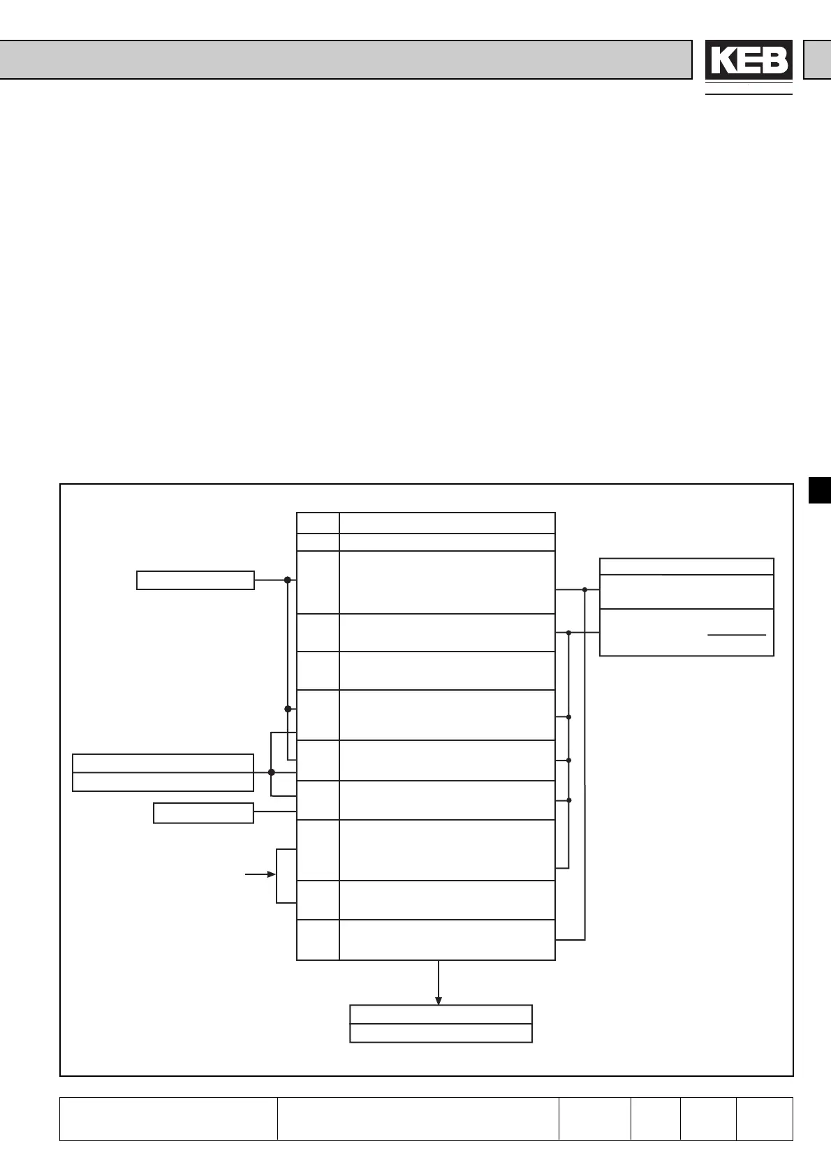
Fig. 6.9.1 Principle of DC-Brake
6.9.1 DC-Brake
At DC-braking the motor is not decelerated by the ramp. The fast braking occurs
through DC voltage, which is given on the motor winding.
Between the activation and the triggering of the DC-braking a time constant called
Base-Block-Time (bbL) of 150…1500 ms (depending on the motor size) is required.
It serves for the protection of the power modules during the motor de-excitation time.
The trigger for the DC-braking is adjusted with Pn.8. Corresponding to the adjusted
mode a frequency can be adjusted with Pn.9, at which the DC-Brake engages.Pn.11
determines the time of braking. With Pn.10 the maximum braking voltage is adjusted.
For that the brake controllers are designed for a 1:1 dimensioning of inverter to motor,
consequently the maximum braking voltage must be reduced in case of deviating
dimensioning in order to avoid an overheating of the motor. At large capacities the
maximum braking voltage can lead to overcurrent errors (OC). In that case reduce
Pn.10.
The following section shall facilitate the adjustment and programming of special
functions.
Pn.11 DC-Brake / Time
Set braking time= 0...100s
Actual braking time=
Pn.11 · fist
100 Hz
Pn.8 DC-Braking/Aktivation
0 DC-Braking not activated
1 DC-Braking after attaining ru.3 = 0Hz and
missing setting of rotation: maximally for
the adjusted DC-braking time Pn.11
(independent of actual frequency) or up to
the next setting of rotation.
2 DC-Braking as soon as direction of rotation
is missing (braking time depends on actual
frequency ru.3).
3 DC-Braking as soon as direction of rotation
changes (braking time depends on actual
frequency ru.3).
4 DC-Braking as soon as setting of rotation
is missing and actual frequency falls below
the adjusted level Pn.9 (braking time
depends on actual frequency ru.3).
5 DC-Braking as soon as actualfrequency
falls below the adjusted level Pn.9 (braking
time depends on actual frequency ru.3).
6 DC-Braking as soon as setpoint frequency
ru.6 falls below the adjusted level Pn.9
(braking time depends on ru.3)
7 DC-Braking as soon as an input
programmed for DC-braking is active
(di.3...di.10=4), braking time depends on
actual frequency ru.3. Restart only after
deactivating the input.
8 DC-Braking for as long as an input
programmed for DC-braking is active
(di.3...di.10=4).
9 DC-Braking after enabling the modulation
(direction of rotation + control release) for
the adjusted time Pn.11.
ru.3 Actual frequency
Pn.9 DC-Brake / Starting frequency
0...409,5 Hz (default 4Hz)
ru.6 Set frequency
Pn.10 DC-Brake / max. voltage
0...25,5% (default 25,5%)
see function
"Digital Inputs"
di.3...di.10 = Value 3
 Loading...


