3
ANTRIEBSTECHNIK
7
13
KEB COMBIVERT F4-C
Name: Basis
30.01.98
7
© KEB Antriebstechnik, 1997
All Rights reserved
Start-up
Section
Page
Date
Chapter
P
O
W
E
R
X
X
X
X
X
X
X
X
X
X
X
X
I
N
P
U
T
O
U
T
P
U
T
K
E
B
A
n
t
r
i
e
b
s
t
e
c
h
n
i
k
K
a
r
l
E
.
B
r
i
n
k
m
a
n
n
G
m
b
H
D
-
3
2
6
7
7
B
a
r
n
t
r
u
p
M
a
d
e
i
n
G
e
r
m
a
n
y
V
O
L
T
A
G
E
C
Y
C
L
E
X
X
X
X
X
X
X
X
X
X
X
X
X
X
X
X
X
X
X
X
X
X
V
O
L
T
A
G
E
C
U
R
R
E
N
T
V
E
R
-
N
O
.
A
R
T
-
N
O
.
S
E
R
-
N
O
.
X
X
X
X
X
X
X
X
X
X
X
X
X
X
X
˜
9
5
0
0
0
0
0
1
/
X
X
X
X
X
X
X
X
X
.
F
4
.
X
X
X
-
X
X
X
X
X
X
X
X
X
X
X
X
X
X
X
X
X
X
X
X
X
X
X
X
X
X
A
C
-
M
O
T
.
4
,
0
K
W
,
2
/
4
P
,
5
0
/
6
0
H
Z
L1 L2 L3
2
3
S
T
A
R
T
S
T
O
P
E
N
T
E
R
F
/
R
F
U
N
C
.
S
P
E
E
D
ele
ctro
nic
A
N
TR
IE
B
ST
E
CH
N
I
1
P
OW
E
R
XX
XX
X
XX
XX
X
XX
IN
P
UT
O
U
TP
U
T
KE
B An
trieb
stechnik
Kar
l E
. B
rinkm
ann G
m
bH
D
-326
77 B
arn
tru
p
Made
in G
erm
any
V
OLT
A
G
E
CY
C
LE
X
XX
X
X
XX
X
XX
X
X
X
XX
X
XX
X
XX
X
VO
LT
A
G
E
CURRENT
V
ER
-N
O
.
A
RT
-NO
.
SE
R
-N
O
.
X
XX
X
X
XXX
X
X
XX
X
XX
˜
9
50
00
001
/XX
X
XX
X
X
X
X
.F4.X
XX
-XX
XX
X
XXX
XX
XX
X
XXX
X
X
XX
X
XXX
X
X
A
C-M
O
T
.
4
,0
KW
, 2
/4 P
, 5
0/60 HZ
L
1
L
2
L
3
S
T
A
R
T
S
T
O
P
E
N
T
E
R
F
/
R
F
U
N
C
.
S
P
E
E
D
e
l
e
c
t
r
o
n
i
c
A
N
T
R
IE
B
S
T
E
C
H
N
I
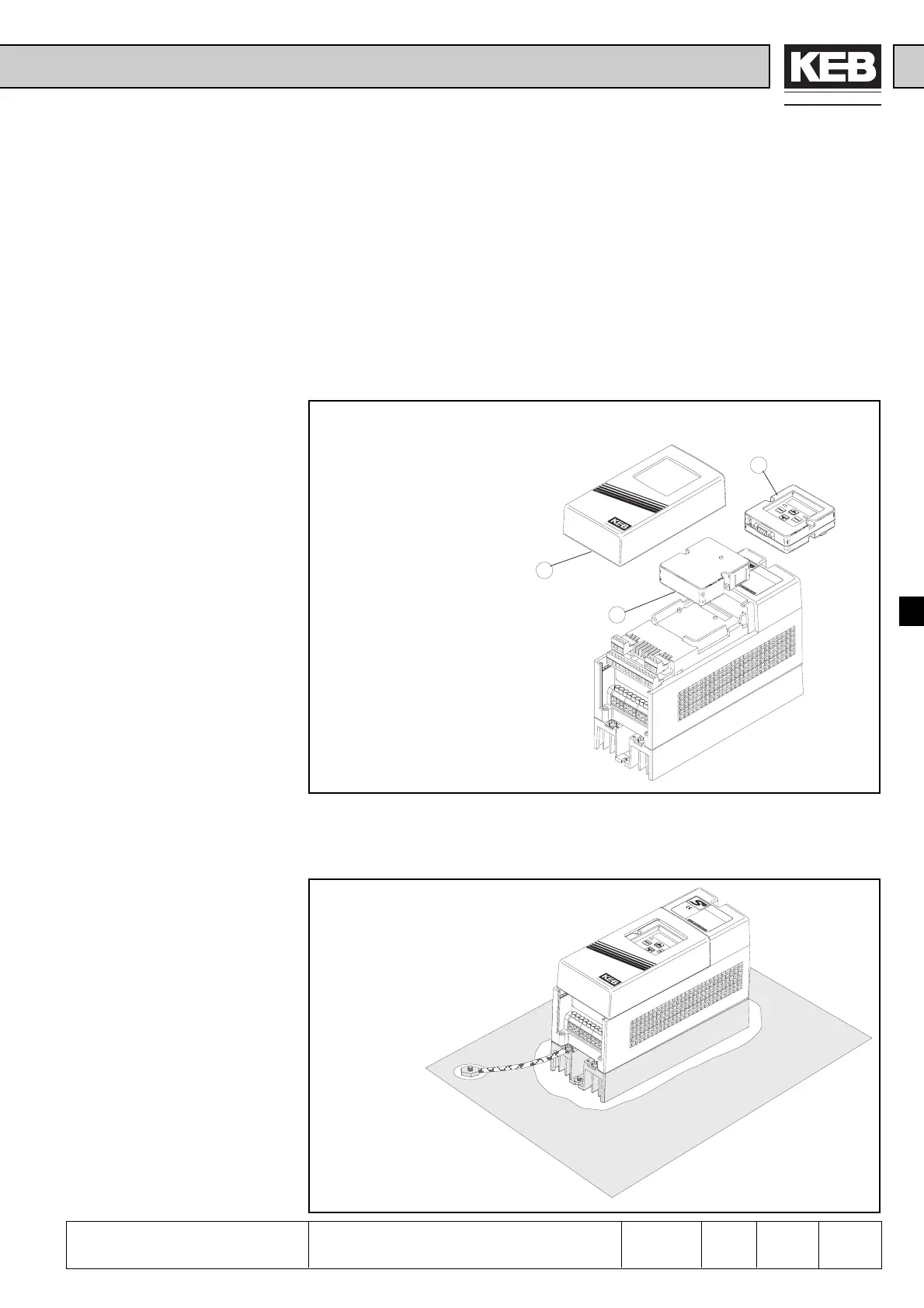
7.1.1 After unpacking
the Goods
7.1 Preparatory
Measures
7.1.2 Installation and
Connection
Picture 7.1.1 Insertion of operator (example based on D-housing)
7. Start-up
The following chapter is intended for everybody who has no experience with the KEB
frequency inverters. It shall allow a correct entering into this field. But because of the
complex application possibilities we must restrict ourselves to explaining the start-up
of standard applications.
After unpacking the goods and checking them for complete delivery following measures
are to be carried out:
þ Visual control for transport damage
þ Insert operator, if ordered
þ Remove housing cover
þ Remove the dummy cap
þ Insert operator
Picture 7.1.2.a Installation and connection
The EMC-conform installation of the inverter is described in the Instruction Manual
Part 1. Installation and connection instructions are found in the Instruction Manual
Part 2.
þ The mounting surface of
the inverter must be
bright.
þ If necessary, use contact
lacquer as protection
against corrosion.
þ Connect the earthing
strip to central point in
the control cabinet.
Preparatory Measures
 Loading...


