6 3
KEB COMBIVERT F4-C
10
Name: Basis
28.01.98
Chapter Section
Page Date
© KEB Antriebstechnik, 1997
All Rights reserved
Functional Description Digital In- and Outputs
1
2 3
RLA
RLB
RLC
X1
max. 30V / 1A DC
OUT2
12
13 14
A
out
0V
U
ext
X1
OUT1
+15V / 100mA
OUT3
21
22 23
FLA
FLB
FLC
X1
max. 30V / 1A DC
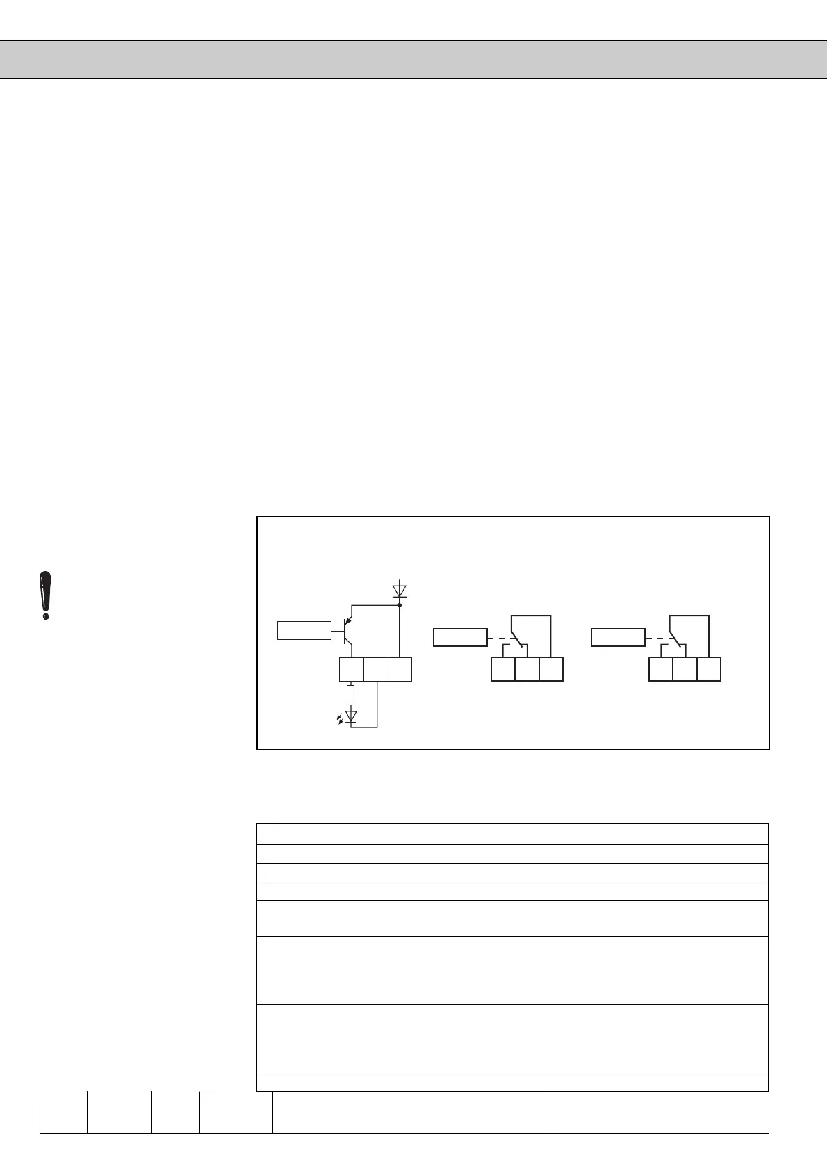
The KEB COMBIVERT has
- 1 Transistor output Out1 terminal X1.12 (AOUT)
- 2 Relay outputs Out2 terminal X1.1 / X1.2 / X1.3 (RLA, RLB, RLC)
Out3 terminal X1.21/ X1.22/ X1.23 (FLA, FLB, FLC)
- 4 internal outpus OA...OD (firmly connected with the inputs IA...ID )
From the 35 different conditions you can choose up to 4 for the switching of the digital
outputs. These are entered in do.1...do.4. Parameter ru.17 indicates, whether one or
several of these conditions are met. For each output it can now be selected which of
the 4 conditions shall be valid (do.9...do.16). You can choose between no condition
or all 4 conditions. For each output every condition can still be inverted before the
selection (do.17...do.24). As standard all conditions (if several are selected) are OR-
linked, i.e. if one of the selected conditions is met, the output switches. With do.25 this
can be changed into AND-function, i.e. all of the conditions selected for the output
must be met, before it is set. Parameter do.0 serves to negate one or several outputs.
ru.15 serves for the indication of the real or through negating switched outputs. The
internal outputs (OA...OD) are directly connected with the internal inputs IA...ID (see
picture 6.3.1).
6.3.14 Output Signals
Picture 6.3.14 Connection of digital outputs
6.3.15 Output Conditions
(do.1...do.4)
From the following switching conditions up to 4 conditions can be selected for further
processing. The values are then entered in parameters do.1...do.4.
ValueFunction
0 off
1 always active
2 Faul relay trips when inverters switches off with error
3 Fault relay, like 2, but not for errors, that are automatically reset at activated
„Auto-Restart function“
4 Overload Warning! ru.24 is an overload counter that counts in steps of 1 %.
At 100 % the inverter switches off. With LE.32 a percentual value can be
adjusted, at which the inverter shows the message (standard value 80%
overload).
5 Overheating Warning! Depending on the power circuit the inverters switch
off at a temperature between 70...90°C with error Overheating. With LE.34
any value between 0...100°C can be adjusted at which the warning shall be
given.
At transistor output X1.12 a
current of 50mA can be taken,
so that 50mA remain for the
supply of the digital inputs!
At inductive load on the relay
outputs or the trasistor output
a protective wiring must be
provided (freewheeling diode).
 Loading...


