6 2
KEB COMBIVERT F4-C
6
Name: Basis
Chapter Section
Page Date
© KEB Antriebstechnik, 1999
All Rights reserved
16.02.00
Functional Description Analog In- and Outputs
100%
100%
-100%
-100%
100%
100%
-100%
-100%
An.10
50%
100%
100%
-100%
-100%
An.9
1. 2.
An.11=100%
100%-100%
An.10=75%
An.9
6.2.5 Input
characteristics
Amplifier
(An.3...5,
An.9...11,
An.23...25)
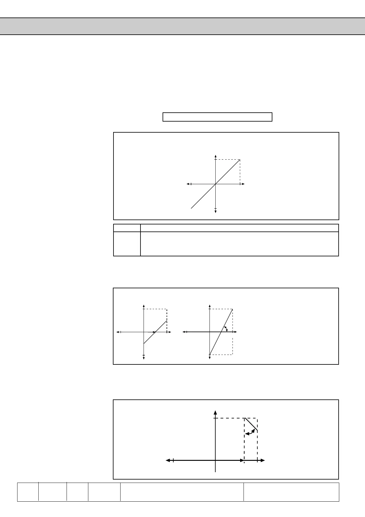
You can see in picture 6.2.1 the characteristics amplifiers are the next to the buffer
memory. With these parameters the input signals can be adjusted with a x- and y-
offset and also a gain. No offset is adjusted with factory setting. The gain is 1, i.e. the
input value is equivalent to the output value (see picture 6.2.5.a). The output value
depends on the following formula:
Out = Gain ( In - Offset X ) + Offset Y
Input value (In)
Output value (Out)
Picture 6.2.5.a Factory setting: no Offset, Gain 1
With these examples we want to show you the possibilities of these functions. In
accordance with picture 6.2.5.b
1. set the X-Offset for the input REF at 50 (%)
2. set the Gain at 2 (-times amplification)
Picture 6.2.5.b X-Offset (An.10)=50%; Gain (An.9)=2.00
Input ±REF REF Option Range of ValuesResolution Standard Value
Gain An.3 An.9 An.23 -20...20 0,01 1,00
X-Offset An.4 An.10 An.24 -100...100 0,1 0
Y-Offset An.5 An.11 An.25 -100...100 0,1 0
With these adjustments the whole
speed range can be driven via the
input REF. (direction of rotation = ±ana-
log)
0% In corresponds to -100% Out
50% In corresponds to 0% Out
100% In corresponds to 100% Out
In accordance with picture 6.2.5.c
1. set the X-Offset for the input REF to 75 (%)
2. set the Y-Offset for the input REF to 100 (%)
2. set the Gain to -1(-times amplification)
Picture 6.2.5.c X-Offset (An.10)=75%; Y-Offset (An.11)= 100%; Gain (An.9)= -1.00
 Loading...


