3
ANTRIEBSTECHNIK
10
13
KEB COMBIVERT F4-C
Name: Basis
31.03.98
10
Project Planning
Section PageDate
© KEB Antriebstechnik, 1997
All Rights reserved
Chapter
30
150
100
F4 F4
KEB
COMBIVERT
10.1 General Design
10. Project
Planning
The following chapter shall assist you in the planning stage of applications.
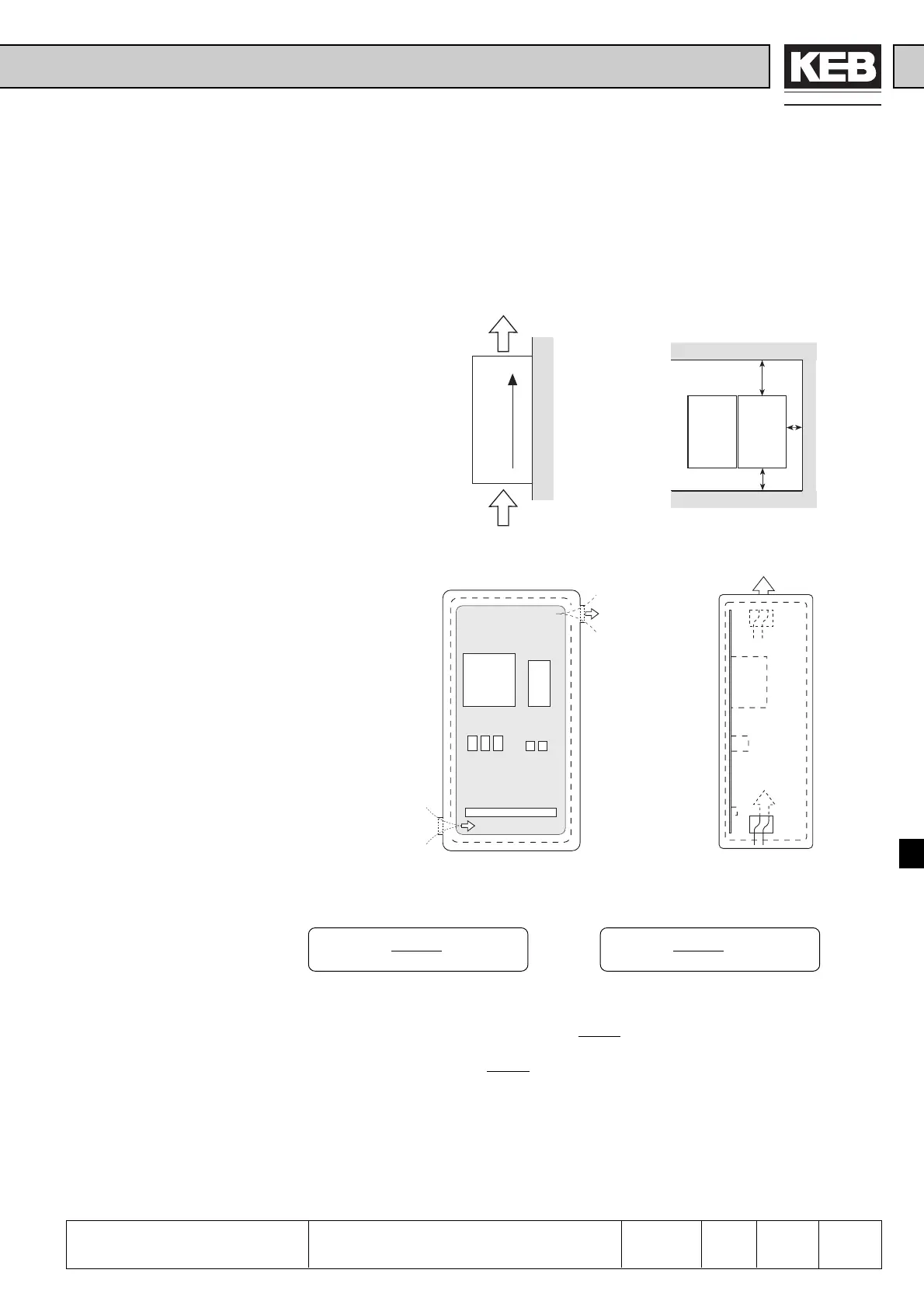
10.1.1 Control Cabinet
Design
Calculation
Control cabinet surface
Calculation of control cabinet surface:
P
V
A = [m
2
]
∆T • K
Air flow rate with fan cooling :
3,1 • P
V
V = [m
3
/h]
∆T
A = control cabinet surface [m
2
]
∆T = temperature differential [K]
(standard value= 20 K)
K = coefficient of heat transmission
(standard value = 5 )
P
V
= power loss (see Technical Data)
V = air flow rate of fan
For more details please refer to the catalogs of the control cabinet manufacturers.
W
[]
m
2
• K
Direction of cooling fins
Minimum
distances
Warm air
outlet
Cool air inlet
W
m
2
• K
 Loading...


