7
ANTRIEBSTECHNIK
610 7
KEB COMBIVERT F4-C
Name: Basis
19.11.98
6
Section
Page
Date
© KEB Antriebstechnik, 1997
All Rights reserved
Chapter
Functional DescriptionEncoder Interface
123
0V
U
Ext
Fig. 6.10.5.b Block diagram of initiator input
R
i
:1.9 kΩ
U
in
(max.): U
ext
T
Puls
(min.): 25 µs
Terminal 1: U
ext
Terminal 2: Initiator signal
Terminal 3: 0V
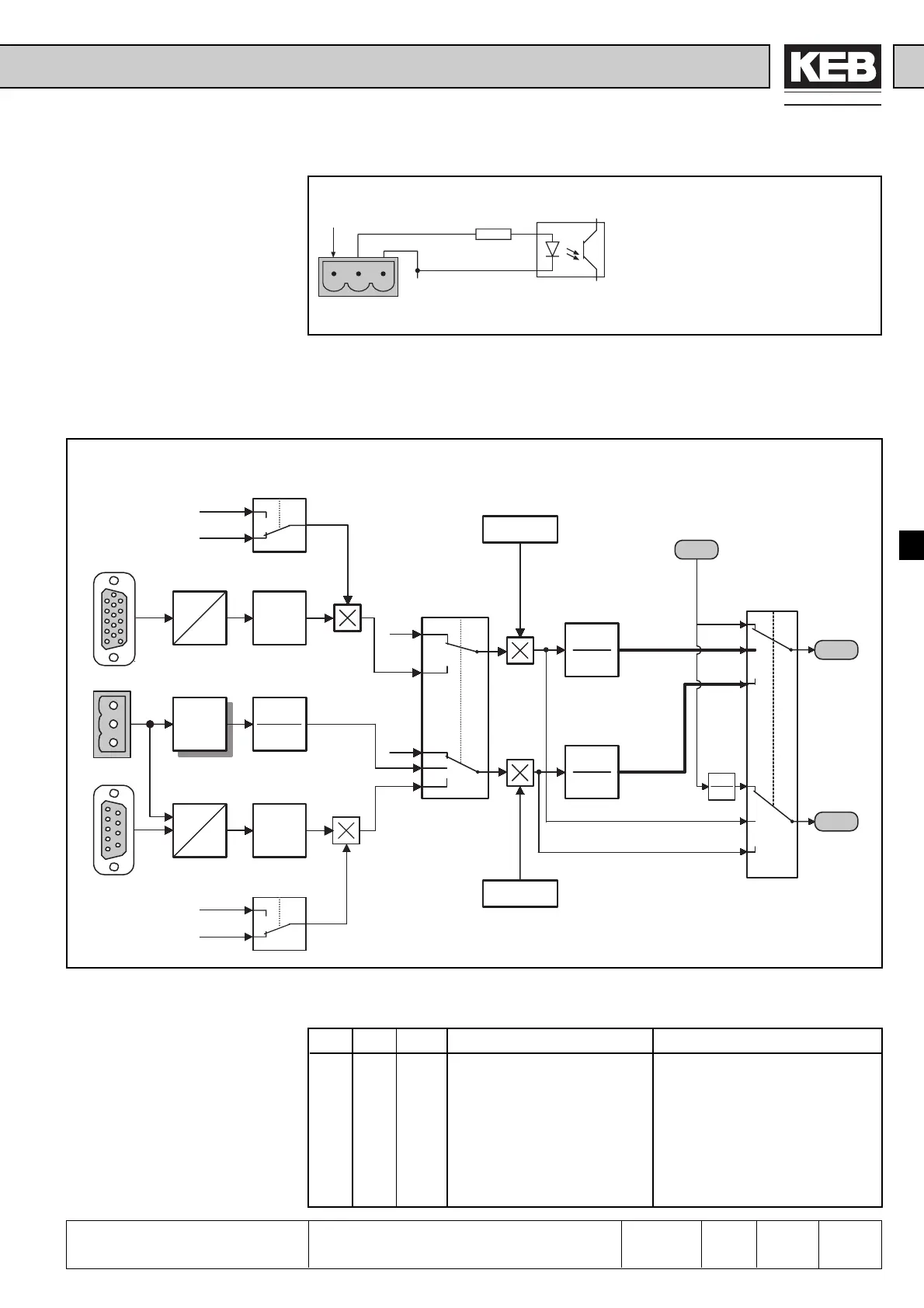
6.10.6 Speed
Measurement
In the following the range from the input terminals of the interface card up to the as
setpoint value or actual value analyzable speeds and frequencies is referred to as
speed measurement. Fig. 1 shows the signal flow and the intervention possibilities of
the speed measurement.
INC
n
INC
n
Filter
Filter
Processing
of the analog
inputs
Chap. 6.2
-1
1
dr.29
dr.37
dr.25
dr.30 dr.38
X5
X4
X5
0
1
dr.44
100%
dr.24
bit 1,2
0
bit 0
1
2,3
0
1
gear factor
channel1
dr.35
60
PPN
f_ch_1
n_ch_1
gear factor
channel2
dr.36
60
PPN
f_ch_2
n_ch_2
PPN
60
0
1
2
0
1
2
ru.47
ru.1
f_out
cn.3
-1
1
dr.34
1
0
off
off
ru.3
r
e
a
l
v
a
l
u
e
Fig. 6.10.6.a Summary of speed measurement
Central parameter of the speed measurement is dr.24. This parameter must be adjusted
according to the installed interface card.
Value bit 0 bit 1,2 Channel 1 Channel 2
0 0 0 no detection no detection
1 1 0 Incremental encoder input 1 no detection
2 0 1 no detection Tacho input (±10V input)
3 1 1 Incremental encoder input 1 Tacho input (±10V input)
4 0 2 no detection Incremental encoder input 2
5 1 2 Incremental encoder input 1 Incremental encoder input2
6 0 3 no detection Initiator input
7 1 3 Incremental encoder input 1 Initiator input
Defintion of the Hardware
Attention, adjust motor data !
The inverter gets the pole pair number (PPN)
from dr.3 / dr.1 * 60 (also see chap. 6.6.3)
Don’t forget, 4 poles = 2 pole pairs !
 Loading...


