6 3
KEB COMBIVERT F4-C
6
Name: Basis
28.01.98
Chapter Section
Page Date
© KEB Antriebstechnik, 1997
All Rights reserved
Functional Description Digital In- and Outputs
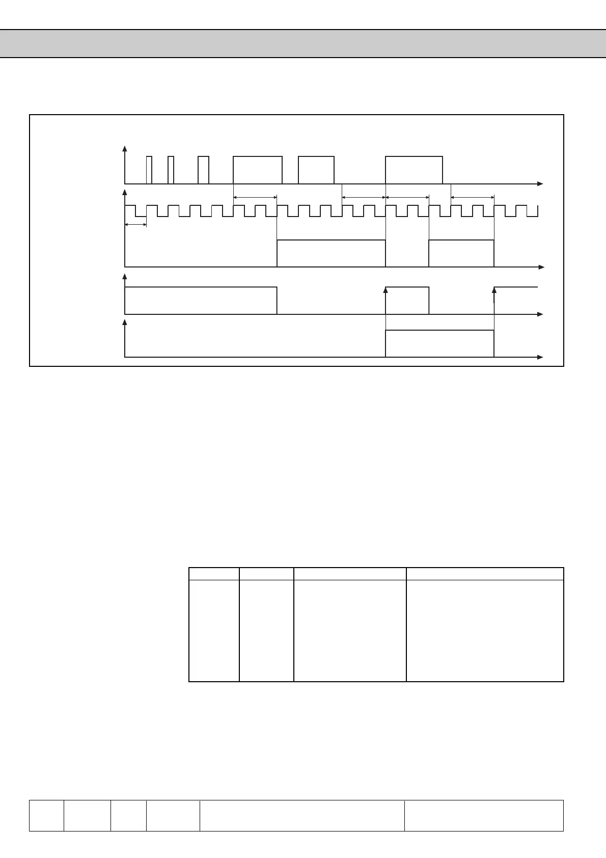
4ms
8ms 8ms
t
t
8ms 8ms
t
t
Input signal
Digital filter
Inverted signal
Input status by edge
triggering
6.3.8 Strobe-
dependent
Inputs(di.17...di.19)
Mostly a strobe signal is used for triggering the input signals. For example, two inputs
shall serve for a parameter set selection. The signals for actication do not arrive at
exactly the same time, so for a short time it would be switched in an unintended set.
With active strobe (sampled signal) the actual input signals of the strobe-dependent
inputs are accepted and retained unitl the next scanning.
With di.17 every input can be selected as strobe-dependent input. di. 17 has no
function for the control release, because it is a static input.
With parameter di.18 every input can be adjusted as strobe in addition to its
programmable function. If there are several inputs adjusted as strobe, these are OR-
logic. With the next rising edge of the clock signal, the strobe is triggered.
Terminal Name Function Decimal Values di.17 and di.18
X1.19 ST (Control release) 1
X1.20 RST (Reset) 2
X1.10 F (Forward) 4
X1.11 R (Reverse) 8
X1.4 I1 (Prog. Input 1) 16
X1.5 I2 (Prog. Input 2) 32
X1.6 I3 (Prog. Input 3) 64
di.17 Strobe-dependent Inputs
di.18 Selection of Strobe Signal
Where is the Strobe Signal
coming from?
Which Inputs are switched by
Strobe?
Picture 6.3.7 Example of a signal transit-plan for Input I1 (di.0=2; di.2=16; di.14=16)
 Loading...


