5 1
KEB COMBIVERT F4-C
8
Name: Basis
Chapter
Section Page Date
© KEB Antriebstechnik, 1997
All Rights reserved
20.03.98
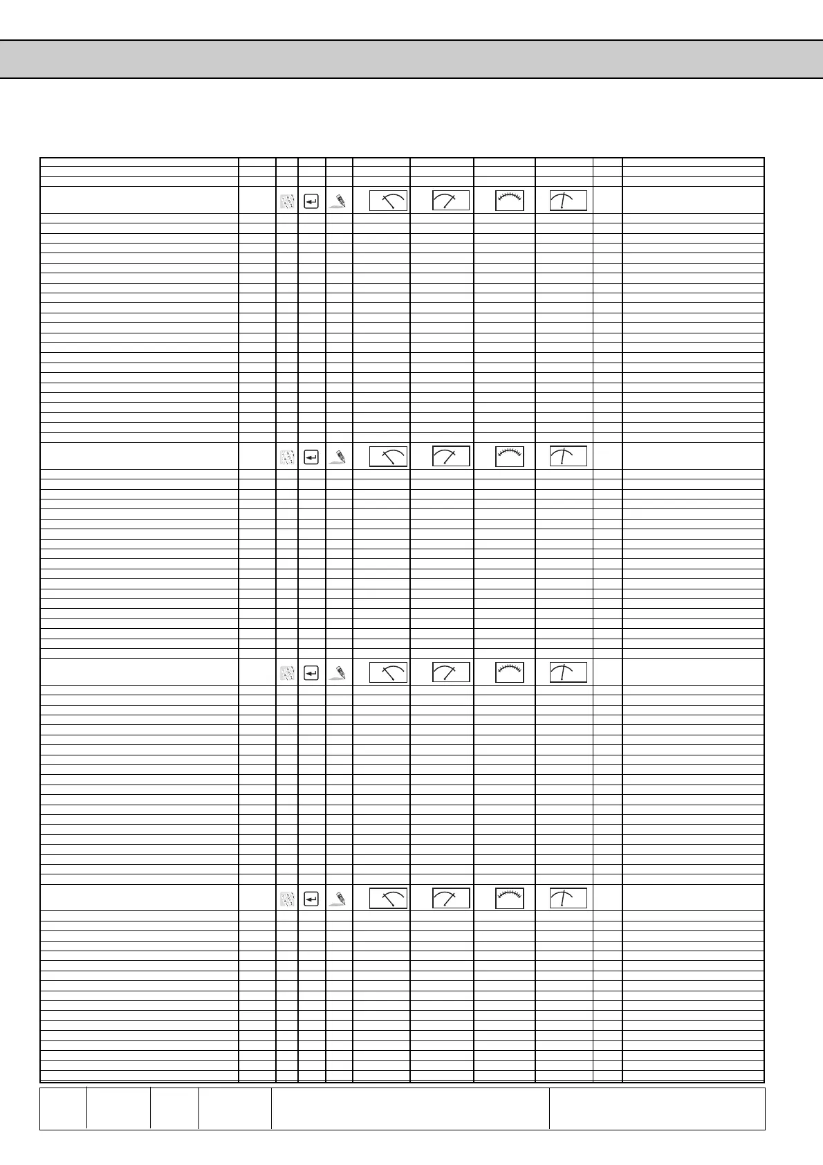
Parameter
Fr 5 Parameter Set Activation Delay 2705 √ - √ 0 2,55 0,01 0 sec 6.8.7
Fr 6 Parameter Set Deactivation Delay 2706 √ - √ 0 2,55 0,01 0 sec 6.8.7
Fr 9 Bus Parameter Set 2709 - - √ -1 : act. 7 1 0 - 6.8.3
An - Parameter Addr.
min
max
default
[?] see page(s)
An 1 Noise Filter Ref 1 2801 - - √ 0 4 1 0 - 6.2.4; 6.2.10
An 2 Zero Clamp Ref 1 2802 - - √ -10,0 10,0 0,1 0,2 % 6.2.7; 6.2.10
An 3 Ref 1 Gain 2803 - - √ -20,00 20,00 0,01 1,00 - 6.2.6; 6.2.10
An 4 Ref 1 Offset X 2804 - - √ -100,0 100,0 0,1 0,0 % 6.2.6; 6.2.10
An 5 Ref 1 Offset Y 2805 - - √ -100,0 100,0 0,1 0,0 % 6.2.6; 6.2.10
An 6 Ref 2 - Interface - Definition 2806 - √√ 0 2 1 0 - 6.2.4; 6.2.10
An 7 Noise Filter Ref 2 2807 - - √ 0 4 1 0 - 6.2.4; 6.2.10
An 8 Zero Clamp Ref 2 2808 - - √ -10,0 10,0 0,1 0,2 % 6.2.7; 6.2.10
An 9 Ref 2 Gain 2809 - - √ -20,00 20,00 0,01 1,00 - 6.2.6; 6.2.10
An 10 Ref 2 Offset X 280A - - √ -100,0 100,0 0,1 0,0 % 6.2.6; 6.2.10
An 11 Ref 2 Offset Y 280B - - √ -100,0 100,0 0,1 0,0 % 6.2.6; 6.2.10
An 12 Reference/Aux Selection 280C √√ √ 0 1 1 0 - 6.2.7; 6.2.10
An 13 Aux Function 280D √√ √ 0 6 1 1 - 6.4.5
An 14 Analog Out1 Function 280E √ - √ 0 6 1 0 - 6.2.8; 6.2.10
An 15 Analog Out1 Gain 280F √ - √ -20,00 20,00 0,01 1,00 - 6.2.8; 6.2.9; 6.2.10
An 16 Analog Out1 Offset X 2810 √ - √ -100,0 100,0 0,1 0,0 % 6.2.8; 6.2.9; 6.2.10
An 17 Analog Out1 Offset Y 2811 √ - √ -100,0 100,0 0,1 0,0 % 6.2.8; 6.2.9; 6.2.10
An 22 Analog In Mode 2816 - √√ 0 255 1 0 - 6.2.5; 6.2.7; 6.2.8; 6.2.10; 6.10.9
An 23 Analog Option Gain 2817 - - √ -20,00 20,00 0,01 1,00 - 6.2.6; 6.2.10; 6.10.9
An 24 Analog Option Offset X 2818 - - √ -100,0 100,0 0,1 0,0 % 6.2.6; 6.2.10; 6.10.9
An 25 Analog Option Offset Y 2819 - - √ -100,0 100,0 0,1 0,0 % 6.2.6; 6.2.10; 6.10.9
An 26 Noise Filter Analog Option 281A - - √ 0 4 1 0 - 6.2.4; 6.2.10
An 27 Zero Clamp Analog Option 281B - - √ 0,0 10,0 0,1 0,2 % 6.2.7; 6.2.10
di - Parameter Addr.
min
max
default
[?] see page(s)
di 0 Noise Filter Digital 2900 - - √ 0 31 1 0 - 6.3.3; 6.3.5
di 1 NPN/PNP Selection 2901 - √√ 0 : pnp 1 : npn 1 0 : pnp - 6.3.3
di 2 Input Logic 2902 - √√ 0 255 1 0 - 6.3.3; 6.3.5
di 3 Input Function I1 2903 - √√ 0 16 1 9 - 6.3.3; 6.3.8; 6.4.11
di 4 Input Function I2 2904 - √√ 0 16 1 9 - 6.3.8; 6.4.11
di 5 Input Function I3 2905 - √√ 0 16 1 3 - 6.3.8
di 6 Input Function I4 2906 - √√ 0 16 1 4 - 6.3.3; 6.3.8
di 7 Input Function IA 2907 - √√ 0 16 1 0 - 6.3.3; 6.3.8
di 8 Input Function IB 2908 - √√ 0 16 1 0 - 6.3.8
di 9 Input Function IC 2909 - √√ 0 16 1 0 - 6.3.8
di 10 Input Function ID 290A - √√ 0 16 1 0 - 6.3.3; 6.3.8
di 14 Input Trigger 290E - √√ 0 255 1 0 - 6.3.3; 6.3.5
di 15 Select Signal Source 290F - √√ 0 255 1 0 - 6.3.3; 6.3.4; 6.3.5
di 16 Digital Input Setting 2910 - √√ 0 255 1 0 - 6.3.3; 6.3.4; 6.3.5
di 17 Input Strobe Dependance 2911 - √√ 0 255 1 0 - 6.3.3; 6.3.6
di 18 Select Strobe Source 2912 - √√ 0 255 1 0 - 6.3.6
di 19 Select Strobe Mode 2913 - √√ 0 1 1 0 - 6.3.3; 6.3.7
di 20 Rotation Input 2914 - √√ 0: Run/Stop 2: F/R + release 1 1: F/R - 6.3.3; 6.3.7; 6.4.7
di 21 Reset Mode for ST 2915 - - √ 0: neg. edge 2: no reset 1 0: neg. edge - 6.3.8
do - Parameter Addr.
min
max
default
[?] see page(s)
do 0 Output Logic 2A00 √√ √ 0 255 1 0 - 6.3.13
do 1 Output Condition 1 2A01 √√ √ 0 37 1 14 - 6.1.11; 6.7.3
do 2 Output Condition 2 2A02 √√ √ 0371 2-
do 3 Output Condition 3 2A03 √√ √ 0371 20-
do 4 Output Condition 4 2A04 √√ √ 0371 0-
do 9 Select Out 1 Condition 2A09 √√ √ 0 15 1 1 - 6.3.12
do 10 Select Out 2 Condition 2A0A √√ √ 0 15 1 2 - 6.3.12
do 11 Select Out 3 Condition 2A0B √√ √ 0 15 1 4 - 6.3.12
do 13 Select Out A Condition 2A0D √√ √ 0 15 1 0 - 6.3.12
do 14 Select Out B Condition 2A0E √√ √ 0 15 1 0 - 6.3.12
do 15 Select Out C Condition 2A0F √√ √ 0 15 1 0 - 6.3.12
do 16 Select Out D Condition 2A10 √√ √ 0 15 1 0 - 6.3.12
do 17 Out 1 Condition Logic 2A11 √√ √ 0 15 1 0 - 6.3.12
do 18 Out 2 Condition Logic 2A12 √√ √ 0 15 1 0 - 6.3.12
do 19 Out 3 Condition Logic 2A13 √√ √ 0 15 1 0 - 6.3.12
do 21 Out A Condition Logic 2A15 √√ √ 0 15 1 0 - 6.3.12
do 22 Out B Condition Logic 2A16 √√ √ 0 15 1 0 - 6.3.12
do 23 Out C Condition Logic 2A17 √√ √ 0 15 1 0 - 6.3.12
do 24 Out D Condition Logic 2A18 √√ √ 0 15 1 0 - 6.3.12
do 25 Output Condition Connection 2A19 √√ √ 0 255 1 0 - 6.3.12
LE - Parameter Addr.
min
max
default
[?] see page(s)
LE 0 Frequency Level 1 2B00 √ - √ 0,0000 409,5875 0,0125 0,0000 Hz 6.3.11
LE 1 Frequency Level 2 2B01 √ - √ 0,0000 409,5875 0,0125 4,0000 Hz 6.3.11
LE 2 Frequency Level 3 2B02 √ - √ 0,0000 409,5875 0,0125 4,0000 Hz 6.3.11
LE 3 Frequency Level 4 2B03 √ - √ 0,0000 409,5875 0,0125 50,0000 Hz 6.3.11
LE 8 Load Level 1 2B08 √ - √ 0 200 1 50 % 6.3.11
LE 9 Load Level 2 2B09 √ - √ 0 200 1 100 % 6.3.11
LE 10 Load Level 3 2B0A √ - √ 0 200 1 100 % 6.3.11
LE 11 Load Level 4 2B0B √ - √ 0 200 1 100 % 6.3.11
LE 16 Active Current Level 1 2B10 √ - √ 0,0 370,0 0,1 0,0 A
LE 17 Active Current Level 2 2B11 √ - √ 0,0 370,0 0,1 0,0 A
LE 18 Active Current Level 3 2B12 √ - √ 0,0 370,0 0,1 0,0 A
LE 19 Active Current Level 4 2B13 √ - √ 0,0 370,0 0,1 0,0 A
LE 24 DC Voltage Level 1 2B18 √ - √ 100 LTK 1 250 V 6.3.11
LE 25 DC Voltage Level 2 2B19 √ - √ 100 LTK 1 250 V
LE 26 DC Voltage Level 3 2B1A √ - √ 100 LTK 1 250 V
LE 27 DC Voltage Level 4 2B1B √ - √ 100 LTK 1 250 V 6.3.11
LE 32 OL Warning Level 2B20 √ - √ 0 100 1 80 %