Trigger model
NOTE Additional information on measurement query commands to trigger and/or return
readings are provided in Section 13 and Appendix H.
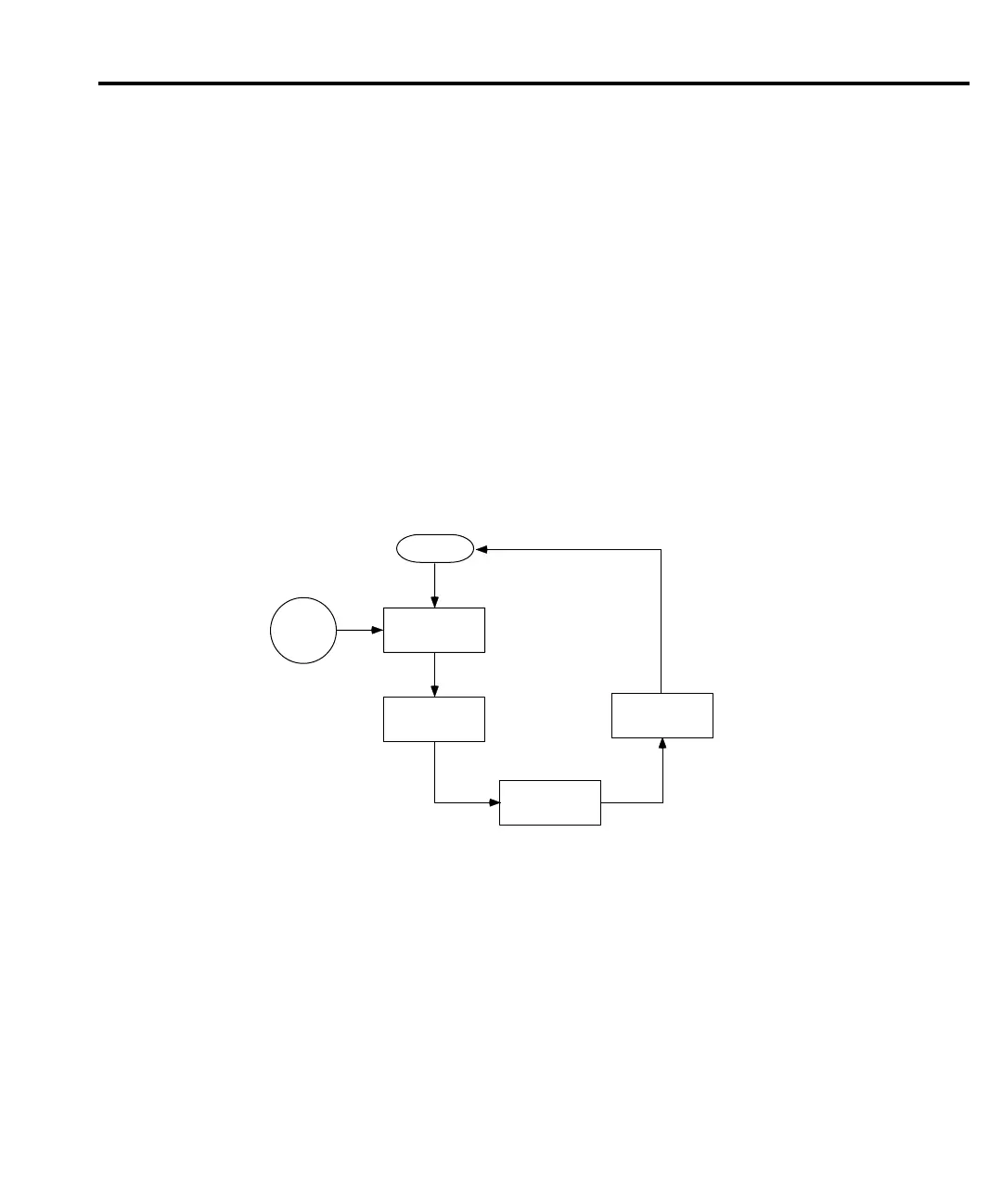
The flowchart in Figure 7-1 summarizes triggering as viewed from the front panel. It is called
a trigger model because it is modeled after the SCPI commands used to control triggering. Note
that for stepping and scanning, the trigger model has additional control blocks. These are
described in Section 9.
NOTE The complete trigger model, which is based on bus operation, is shown and discussed
later in this section (see “SCPI programming - triggering”). Keep in mind that there
is only one trigger model. The ones shown Figure 7-1 and in Section 9 are abbreviated
versions to illustrate front panel operation.
Figure 7-1
Front panel trigger model (without Stepping/Scanning)
Idle
The instrument is considered to be in the idle state whenever it is not performing any
measurements or scanning operations. From the front panel, the unit is considered idle at the end
of a step or scan operation when the reading for the last channel remains displayed. To restore
triggers, press SHIFT and then HALT.
Once the Model 2182 is taken out of idle, operation proceeds through the trigger model.
Idle
Control
Source
Immediate
External
Event
Detection
Delay
Device
Action
Output
Trigger
Triggering 7-3
 Loading...


