Delta, Pulse Delta, and Differential Conductance I-5
Test system configurations
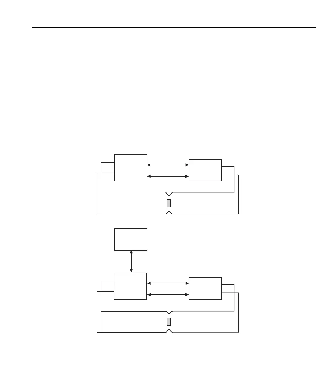
There are two test system configurations that can be used for Delta, Pulse Delta, and
Differential Conductance measurements and are shown in Figure I-2. One is for front
panel stand-alone operation and the other is for remote programming (PC control system).
Both systems use serial communications (via RS-232 interface) between the Model 622x
and the Model 2182/2182A. The Model 622x sends setup commands to the
Model 2182/2182A, and the Model 2182/2182A sends Delta, Pulse Delta, or Differential
Conductance readings to the buffer of the Model 622x. Once the test is started, trigger
synchronization between the two instruments is controlled by the Trigger Link.
Figure I-2
Test system configurations
Trigger Link
Keithley
622x
Keithley
2182/2182A
Current Source
Nanovoltmeter
RS-232
A) Stand-alone system (front panel operation)
Trigger Link
Current Source
Nanovoltmeter
RS-232
B) PC control of 6220/21
PC
(null-modem)
(null-modem)
IEEE-488
or
Ethernet (6221)
RS-232 On
Keithley
2182/2182A
RS-232 On
GPIB or
Ethernet (6221)
Selected
Keithley
622x
GPIB or
Ethernet (6221)
Selected
DUT
Out
Hi
Lo
Ch 1
Hi
Lo
DUT
Out
Hi
Lo
Ch 1
Hi
Lo
 Loading...


