SCPI programming - triggering
Trigger model (remote operation)
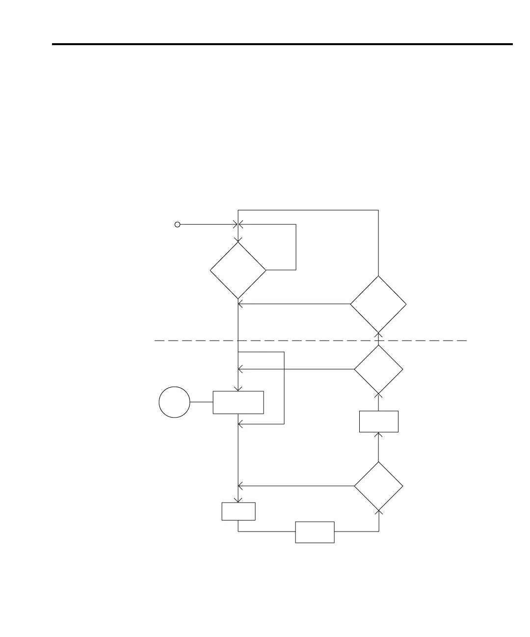
The following paragraphs describe how the Model 2182 operates for remote operation. The
flowchart in Figure 7-10 summarizes operation over the bus. The flowchart is called the trigger
model because operation is controlled by SCPI commands from the Trigger subsystem. Key
SCPI commands are included in the trigger model.
Figure 7-10
Trigger model (remote operation)
:ABOrt
*RCL 0
:SYST:PRES
*RST
No
Yes
Idle
and
Initiate
:Trigger:Signal
Control
Source
:Trigger:Source Immediate
:Trigger:Source External
:Trigger:Source Timer
:Trigger:Source Manual
:Trigger:Source BUS
:Trigger:Delay <n>
:Trigger:Delay:AUTO <b>
Delay
Device
Action
:Sample:Count <n>
Another
Sample
?
:Trigger:Count <n> Infinite
Another
Trigger
?
:INIT (:IMM)
or
:INIT:CONT ON
?
Event
Detection
:INIT (:IMM)
or
:INIT:CONT ON
?
No
No
No
Yes
Yes
Output
Trigger
Yes
START
Triggering 7-13
 Loading...


