Home
Konica Minolta
Measuring Instruments
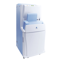
REGIUS 110
Konica Minolta REGIUS 110 Service Manual
4
of 1
of 1 rating
302 pages
Give review
Manual
Specs
To Next Page
To Next Page
To Previous Page
To Previous Page
Loading...
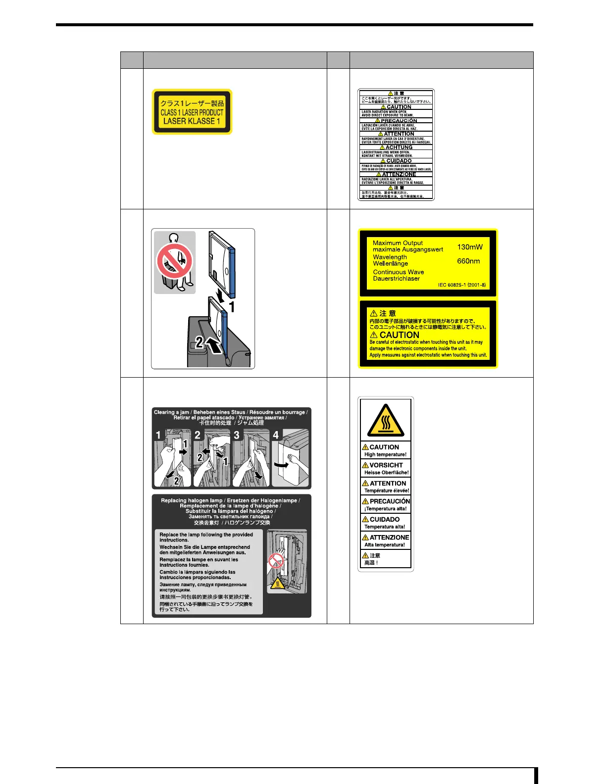
Chapter 1 Safety W
arnings and Cautions
1-3
No.
Contents/W
arning lab
el
No.
Contents/W
arning l
abel
1
Class 1 laser pro
duct
2
Laser caution
3
Do not sit
4
Laser output
5
Clearing a jam and lamp rep
lacement
procedures
6
High T
emperature Caution
14
16
Table of Contents
Default Chapter
4
How to Use this Manual
4
Alert Symbol Marks
5
Signal Words
5
Table of Contents
7
Chapter 1 Safety Warnings and Cautions
13
Warning Labels
14
Position and Type of Warning Label
14
Safety Caution
17
Caution Based on Ordinance
17
General Caution
18
Caution for Handling the Equipment
19
Caution for Handling the Cassette
19
Caution During Service
20
Treatment of Disposed Parts
20
Chapter 2 Before the Repair
22
Name of Parts
22
Structure
24
Principal Specifications
25
Equipment Specification
25
Read/Erase of the Image
26
Control Unit Performance
28
Block Diagram
29
Position of Major Components
31
Insertion Unit
31
Receiver Unit
32
Transporter Unit
33
Subscan Unit
34
Optical Unit/Eraser Unit
35
Detach Detection Unit
36
Exterior
37
Framework
39
Operation
40
Operation Transition Diagram
40
Normal Operation (Image Read Action)
42
Initialization Action
47
Erase Action
50
Optical Unit Maintenance Status
50
Handling the Cassette
51
Tools, Measuring Devices, Jigs, Etc., Necessary for Service
52
Chapter 3 Troubleshooting
56
Workflow
56
Restore Operation
57
Description of the Error Codes and How to Respond
59
06000 ~ 06037: Justifier Motor Errors
59
06050 ~ 06090: Receiver Motor Errors
61
06100 ~ 06143: Transporter Motor Errors
63
06150 ~ 06182: Subscan Motor Errors
67
06200 ~ 06231: Insertion Shuttermotor Errors
69
06250 ~ 06282: Lock Release Motor Errors
70
06300 ~ 06333: Justifier Sensor Errors
71
06350 ~ 06385: Receiver Sensor Errors
73
06400 ~ 06432: Back Plate Detection Sensor Errors
74
06450 ~ 06483: Detach Detection Sensor Errors
75
06500 ~ 06533: Insertion Slot Detection Sensor Errors
76
06550 : Optical Unit/Eraser Unit Errors
78
06600: Fan Error
78
06650 ~ 06683: FPGA Errors
79
14000 ~ 15000: Signal Process Errors
80
23000 ~ 23900: Program Errors
81
24000 ~ 25200: Network Errors
81
26000 ~ 26900: Operation Errors
82
Confirm the H-Sync Signal
84
Confirm the LMC Operation
85
Response to the Problems Not Displaying Error
86
Network Related
86
Power ON/OFF Related
88
Signal Processing Related
91
How to Respond on Image Defect
92
Flow of Response
92
Image Is Dark or Black in General (Still with Structure of the Object)
94
Image Is Bright or White in General (Still with Structure of the Object)
94
Horizontal Streak in Part of the Image
95
Horizontal Streak All over the Image
96
Vertical Streak
97
Quasi-Contour in the Image
98
Jitter (Jagged Vertical Line) in the Image
98
Image Size Is Different (Vertically)
98
Image Size Is Different (Horizontally)
99
Top and Bottom of the Image Is Trimmed
99
Sides of the Image Is Trimmed
99
Unevenness Is Not Calibrated
99
Unevenness Calibration Data Is too High (MAX-MIN Is over 300 Steps)
99
S Value Fluctuation
100
Not Enough Contrast (Raw Data)
100
Different Density Left to Right
100
Dosage Problem (Compatibility Problem with Mas Value and S Value, Etc.)
100
Sandy Image
101
White Dot
101
Black Dot
101
Monitor Display Problem (Film Is OK)
101
Duplex Image
101
Sensitivity Calibration Do Not Fit Within Specification
101
All Processed Images Are Generally High in Contrast
101
All Processed Images Are Generally Low in Contrast
102
Image out of Focus
102
Chapter 4 Confirming Operation Using Service Tool
103
Before Confirming the Operation
104
Outline of Confirming the Operation
104
Display [Unit Test] Screen
105
Display [Unit Test] Screen (in Case of CS-1/CS-2/CS-3)
105
Function Outline of the [Unit Test] Screen
106
Confirming Operation for each Unit
108
Confirming by Step Operation
110
Confirming the Status of the Sensors
119
Chapter 5 Disassembly and Assembly
121
Before Disassembly
122
Precautions During Disassembly/Assembly
122
Basic Works
123
Power OFF/ON
123
Moving the Equipment
125
Removing/Installing the Exterior Panel and Insertion Unit
126
Removing/Installing the Second Front Door
130
Removing/Installing the Optical Unit
131
Moving the Push Plate Unit
137
Binding the Grounding Strap
138
Replacing the Parts on the Insertion Unit
139
Replacing the Operation Unit (Operation Panel)
139
Changing the Mounting Location of the Operation Unit
140
Replacing the Eraser Cooling Fan
142
Replacing the Indicator
143
Replacing the Barcode Reader
144
Replacing the Back Plate Drop Detection Sensor
146
Replacing the Insertion Slot Detection Sensors (LLB)
147
Replacing the Insertion Slot Detection Sensors (LPB)
148
Replacing the Shutter Open Detection Sensor
151
Replacing the Shutter Close Detection Sensor
153
Replacing the Shutter Motor
155
Replacing the Shutter Unit
156
Replacing the Parts on the Receiver Unit
160
Replacing the Justifier HP Sensor
160
Replacing the Justifier Sensor
161
Replacing the Justifier Motor
162
Replacing the Justifier Standard Sensor
164
Replacing the Receiver Sensor
166
Replacing the Receiver HP Sensor
168
Replacing the Receiver Motor
170
Replacing the Lock HP Sensor
172
Replacing the Lock Motor
173
Replacing the Receiver (Receiver Unit Assembly)
175
Replacing the Justifier Guide Unit Assembly
177
Replacing the Receiver Belt
179
Replacing the Justifier Belt
182
Replacing the Parts on the Subscan Unit
185
Replacing the Subscan HP Sensor
185
Replacing the Simple Fixing Unit
187
Replacing the Encoder/Wires
188
Replacing the Tumbler (Lower)
193
Replacing the Cable Bear
194
Replacing the Parts on the Optical Unit
198
Replacing the LMD
198
Replacing the LMC
199
Replacing the Inverter
200
Replacing the Photomultiplier Tube Filter Assy
201
Replacing the Parts on the Eraser Unit
203
Replacing the Erase Lamp Unit (Halogen Lamp)
203
Replacing the Hot-Cathode Tube Lamp
203
Replacing the Halogen Lamp
204
Replacing the Parts on the Detach Detection Unit
206
Replacing the Detach Detection Sensor (Upper)
206
Replacing the Detach Detection Sensor (Lower)
207
Replacing the Detach Detection Roller
209
Replacing the Parts on the Exterior
210
Replacing the Second Front Door Lock Mechanisms
210
Replacing the Interlock Switch
213
Replacing the Noise Filter and the Circuit Protector Unit
214
Replacing the Condenser
217
Replacing the Halogen Power Supply
219
Replacing the PCU
220
Replacing the Transformer Unit Relay (Interlock Relay 1)
221
Replacing the Standby Power Supply Unit Relay (Interlock Relay 2)
222
Replacing the Standby Power Supply
224
Replacing the Analog Power Supply
226
Replacing the Digital Power Supply
227
Replacing the Transformer
229
Replacing the Digital Power Supply Cooling Fan
232
Replacing the MDU Cooling Fan
233
Replacing the Parts on the Framework
235
Replacing the CIU
235
Replacing the MDU
236
Replacing the CF Card
238
Replacing the Transporter HP Sensor
241
Replacing the Transporter Read Sensor
242
Replacing the Transporter Motor
243
Replacing the Back Plate Absorption Detection Sensor
246
Replacing the Brush (Cleaning Unit)
247
Replacing the Tumbler (Upper)
248
Replacing the Back Plate Detection Unit
249
Replacing the Cleaning Unit
250
Chapter 6 Adjustment
254
Adjust Justifier Belt Tension
254
Adjust Receiver Belt Tension
256
Adjustment of Justifier Motor
258
Adjust Wire Tension
262
Adjust Position of Detach Detection Roller/Sensor
264
Adjustment of Pressing Amount
267
Chapter 7 Periodic Maintenance
271
Maintenance Schedule
272
Maintenance Performed Annually
273
Workflow
273
Power off
275
Secure the Maintenance Space
276
Removal of Exterior Panels and Insertion Unit
277
Cleaning Brush and Check for Fallen Foreign Objects
279
Cleaning Cassette Absorption Magnet
280
Greasing LM Guide
281
Greasing Transporter Lead Screw Unit and Transporter Motor Unit Assembly Gear Mechanism Unit
282
Greasing of Release Shaft Holder
283
Greasing Justifier Motor Unit Assembly Gear Mechanism
283
Attachment of Exterior Panels and Insertion Unit
284
Move to the Installed Location
286
Power on
286
Chapter 8 Appendix
288
Service Tool Screen (Unit Test)
288
Indicator] Panel
289
DC Motor] Panel
289
Pulse Motor] Panel
290
Linear Motor] Panel
291
Others] Panel
291
Settings] Panel
292
Adjustment] Panel
293
Monitoring] Panel
294
Global Wiring Diagram
295
Circuit Board Silk Screen Diagram
297
MDU (Mechanism Control Circuit Board)
297
CIU (System Control Circuit Board)
297
LMC (Optical/Subscan Control Circuit Board)
297
LMD (Motor Drive Circuit Board)
297
Contents of Barcode
298
Operation of the Acoustic Wave Tension Meter
299
4
Based on 1 rating
Ask a question
Give review
Questions and Answers:
Need help?
Do you have a question about the Konica Minolta REGIUS 110 and is the answer not in the manual?
Ask a question
Konica Minolta REGIUS 110 Specifications
General
Brand
Konica Minolta
Model
REGIUS 110
Category
Measuring Instruments
Language
English
Related product manuals
Konica Minolta REGIUS 110 HQ
48 pages
Konica Minolta REGIUS 210
6 pages
Konica Minolta REGIUS SIGMA2
76 pages
Konica Minolta CS-7
424 pages
Konica Minolta T-10A
60 pages
Konica Minolta CR-400
160 pages
Konica Minolta CA-310
122 pages
Konica Minolta CM-700d
124 pages
Konica Minolta CM-26dG
156 pages
Konica Minolta CM-2600d
127 pages
Konica Minolta CM-3600A
40 pages
Konica Minolta CHROMA METER
114 pages
 Loading...