Chapter 2 Before the Repair
2-13
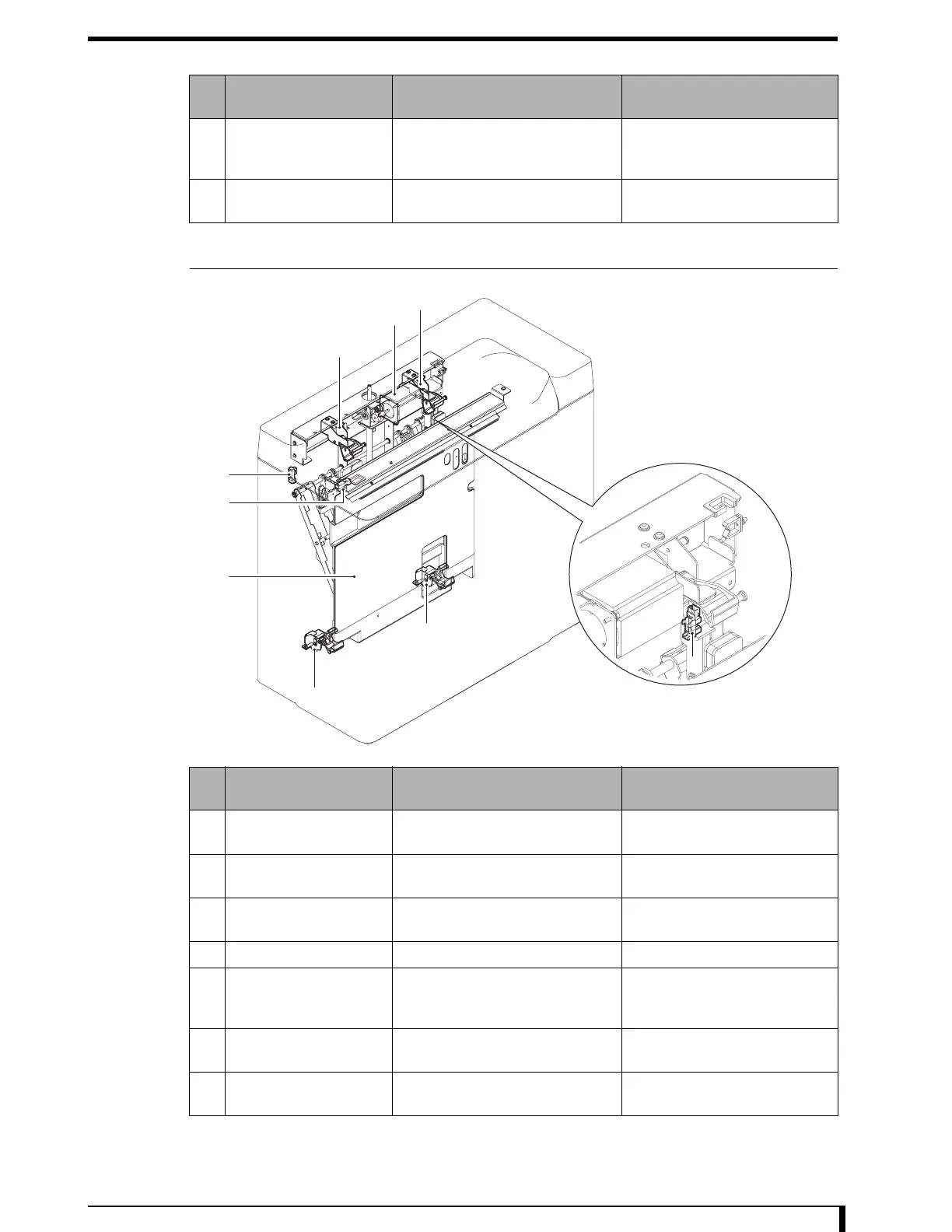
2.5.3 Transporter Unit
*1: Parts attached to the framework.
*2: Parts attached to the subscan unit.
*3: Read position is the position to read/erase the plate, at the first front back side.
11 Lock HP sensor Use to control the operation of
Lock Motor by the FPGA. Initial
position is ON.
"5.4.8 Replacing the Lock HP
Sensor (Page 5-54)"
12 Lock/lock release
mechanism
Operate by Lock Motor, performing
lock/lock release of the cassette.
—
No. Name Function Reference on replacement
method
1 Transporter motor (*1) Move the push plate unit. "5.10.6 Replacing the
Transporter Motor (Page 5-127)"
2 Transporter read sensor
(*1)
It goes ON when the push plate is
at the read position (*3).
"5.10.5 Replacing the Transporter
Read Sensor (Page 5-126)"
3 Transporter HP sensor
(*1)
It goes ON when the push plate
unit is at the home position.
"5.10.4 Replacing the Transporter
HP Sensor (Page 5-125)"
4 Push plate unit
Absorb the back plate of the cassette.
Cannot replace on-site.
5 Back plate absorption
detection sensor (*1)
It goes ON when the push plate is
at the read position (*3) and back
plate is absorbed.
"5.10.7 Replacing the Back Plate
Absorption Detection Sensor
(Page 5-130)"
6 Tumbler (top) (*1) Fix the push plate unit to read
position (*3) with a spring.
"5.10.9 Replacing the Tumbler
(Upper) (Page 5-133)"
7 Tumbler (bottom) (*2) Fix the push plate unit to read
position (*3) with a spring.
"5.5.4 Replacing the Tumbler
(Lower) (Page 5-77)"
No. Name Function Reference on replacement
method
7
7
1
6
6
3
4
2
5
 Loading...